Multiple-pass self-regulating loop heat pipe device

A loop heat pipe and self-regulating technology, applied to indirect heat exchangers, lighting and heating equipment, etc., can solve the problems of inaccurate and flexible temperature control, inability to self-regulate well, and achieve obvious self-regulating ability and maximum The effect of enhanced heat transfer capacity and improved overall pressure drop

Inactive Publication Date: 2007-08-08
SUN YAT SEN UNIV
View PDF2 Cites 34 Cited by
  • Summary
  • Abstract
  • Description
  • Claims
  • Application Information

AI Technical Summary

Problems solved by technology

The heat pipe device introduces a supplementary chamber. Although it can reduce the heat leakage of the system, the single-channel structure of the supplementary chamber cannot control the temperature accurately and flexibly, and cannot self-regulate well.

Method used


Image

  • Multiple-pass self-regulating loop heat pipe device
  • Multiple-pass self-regulating loop heat pipe device
  • Multiple-pass self-regulating loop heat pipe device

Examples


Embodiment 1

[0025] Embodiment 1 Using a flat-plate multi-channel self-regulating loop heat pipe device to dissipate heat from a computer CPU

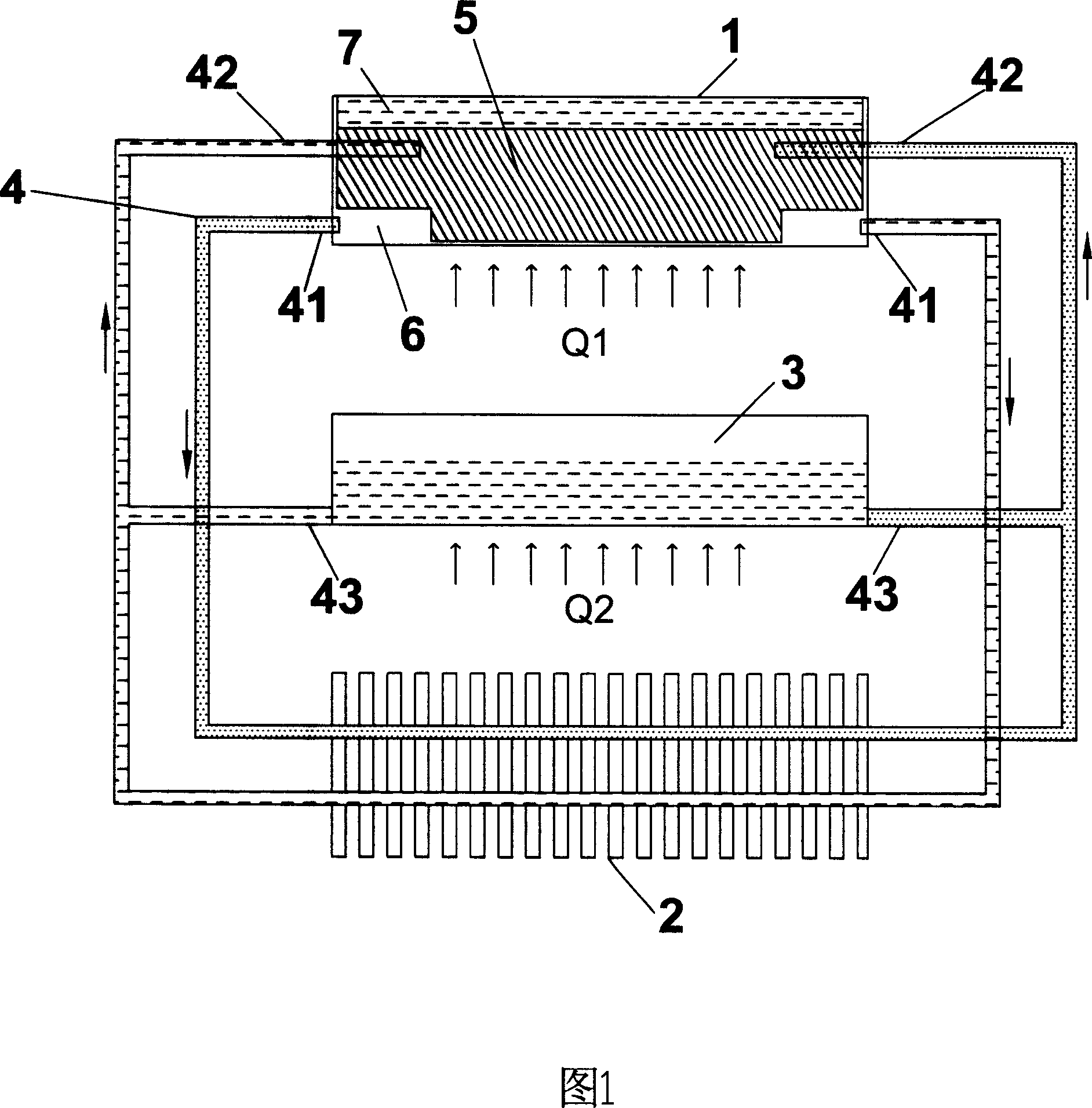
[0026] As shown in Figure 1, a multi-channel self-regulating loop heat pipe device includes an evaporator 1, a condenser 2, a compensator 3 and at least two loop pipes 4; An evaporation chamber 6 is formed between the core 5 and the inner wall of the evaporator 1; the vapor inlet port 41 of the loop pipe 4 communicates with the evaporation chamber 6, the loop pipe 4 passes through the condenser 2, and the return outlet port 42 of the loop pipe 4 communicates with the evaporation chamber 6. The liquid-absorbing core 5 in the device 1 is connected, and the return section 43 of the loop pipe 4 is also connected with the compensator 3, and the compensator 3 is filled with working liquid.

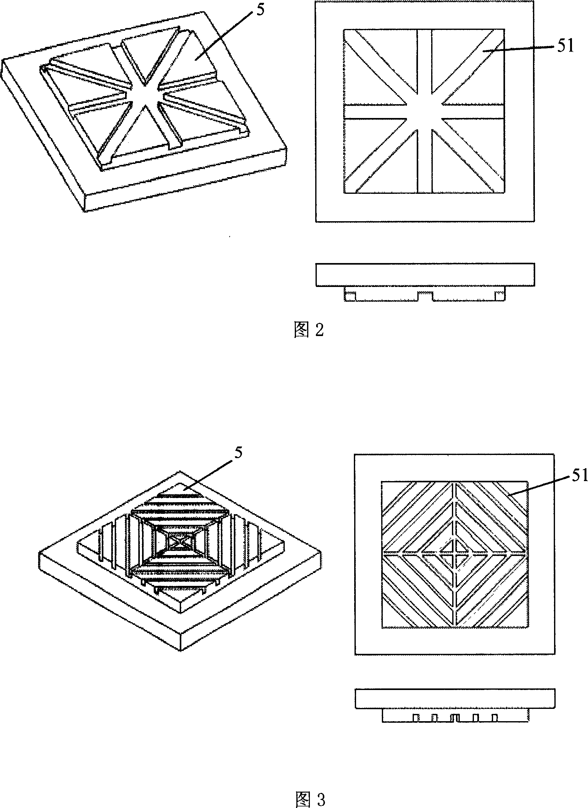
[0027] As a preference, the liquid-absorbing core 5 is designed as a boss structure, and there are positive "V-shaped" or "reverse-V-shaped" channels 51 that communi...

Embodiment 2

[0031] Embodiment 2 Anti-gravity heat dissipation effect of flat plate multi-channel self-regulating loop heat pipe device

[0032] In Fig. 4, when the heat source that needs to dissipate heat is located at the lower part of the evaporator 1, the bottom of the evaporator 1 is in contact with the heat load end Q, the working fluid in the liquid-absorbing core 5 will absorb latent heat, and steam will be generated in the channel 51. The steam finally gathers into the lower evaporation chamber 6, and then reaches the condenser 2 along the loop pipe 4 to be cooled into liquid according to the respective resistance distribution, releases latent heat, and the liquid flows back to the evaporator 1, so as to achieve the purpose of taking away the heat. The suction force of the liquid backflow comes from the liquid suction capacity of the liquid-absorbing core 5 and the gravity effect of the liquid itself.

[0033] In Fig. 5, when the heat source that needs to dissipate heat is located...


PUM


Abstract

The invention discloses a multi-channel self-adjust circuit heat tube, comprising an evaporator, a condenser, a compensator, and at least two loop tubes. The evaporator is arranged with an internal liquid adsorption element which forms an evaporating chamber with the inner wall of evaporator. The steam inlet of loop tube is communicated with the evaporating chamber. The loop tube is through the condenser. The reflux outlet of loop tube is communicated with the evaporator. The reflux section of loop tube is communicated with the compensator filled with working liquid. The invention has high density of heat flow, accurate temperature control and self-adjusting ability.

Description

technical field [0001] The invention relates to the field of heat transfer and cooling of electronic components, in particular to a multi-channel self-regulating loop heat pipe device. Background technique [0002] The loop heat pipe is a new type of two-phase high-efficiency heat transfer device. It uses the capillary force generated by the capillary core in the evaporator to drive the loop to operate, and uses the evaporation and condensation of the working fluid to transfer heat. The case transfers a large amount of heat. [0003] The evaporator of the loop heat pipe is in contact with the heat source, and a high-performance capillary wick (called the first liquid-absorbing wick) is installed inside the evaporator. The compensation chamber is connected to the evaporator, and the two are internally connected through another capillary wick (called the second liquid-absorbing wick). The condensation section is in direct contact with the cold source. The evaporation pipe c...

Claims


Application Information

Patent Timeline
Patent Type & Authority Applications(China)
IPC IPC(8): F28D15/02
CPCF28D15/043
Inventor 吕树申莫冬传金积德涂堂烘
Owner SUN YAT SEN UNIV
Why Eureka
Try Eureka