Optical fibre rotary collector

A technology of rotating connectors and optical fibers, applied in optics, instruments, optical components, etc., can solve problems such as large volume, complex structure of optical fiber alignment mechanism, and difficult installation, so as to achieve free rotation in space, improve work efficiency and reliability , the effect of increasing the degree of freedom

Inactive Publication Date: 2007-08-08
CHINA AVIATION OPTICAL-ELECTRICAL TECH CO LTD
View PDF1 Cites 18 Cited by
  • Summary
  • Abstract
  • Description
  • Claims
  • Application Information

AI Technical Summary

Problems solved by technology

Due to the complex structure of the optical fiber collimatio...

Method used


Image

  • Optical fibre rotary collector
  • Optical fibre rotary collector
  • Optical fibre rotary collector

Examples


Embodiment Construction

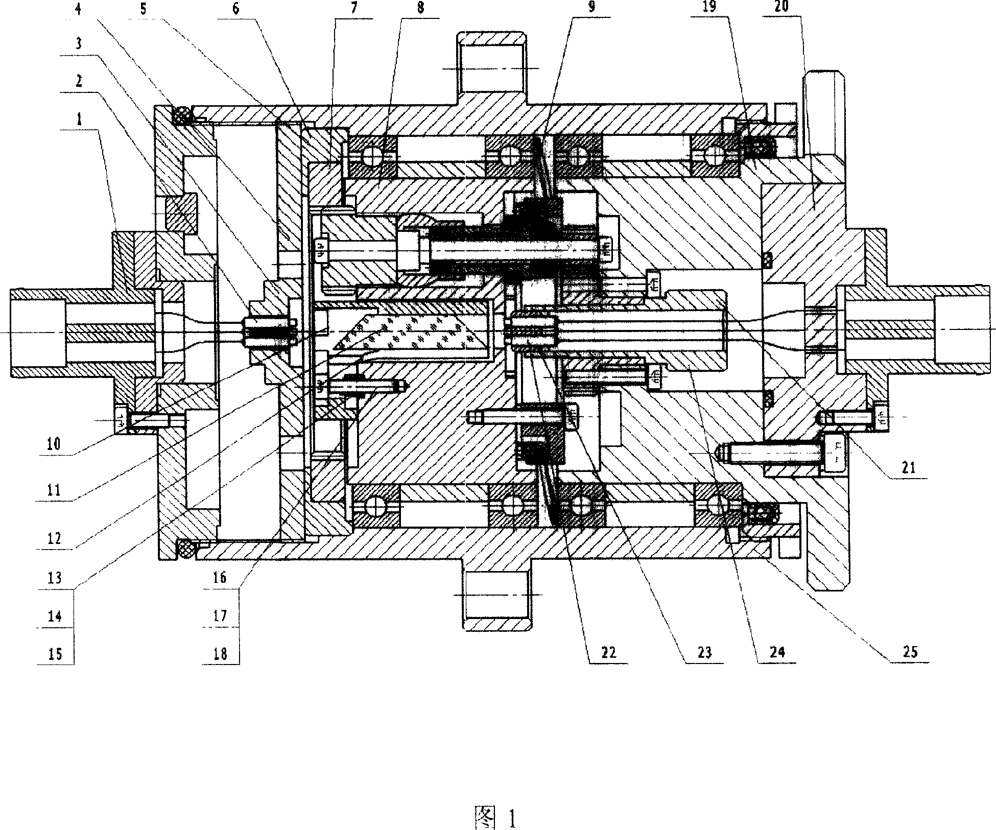
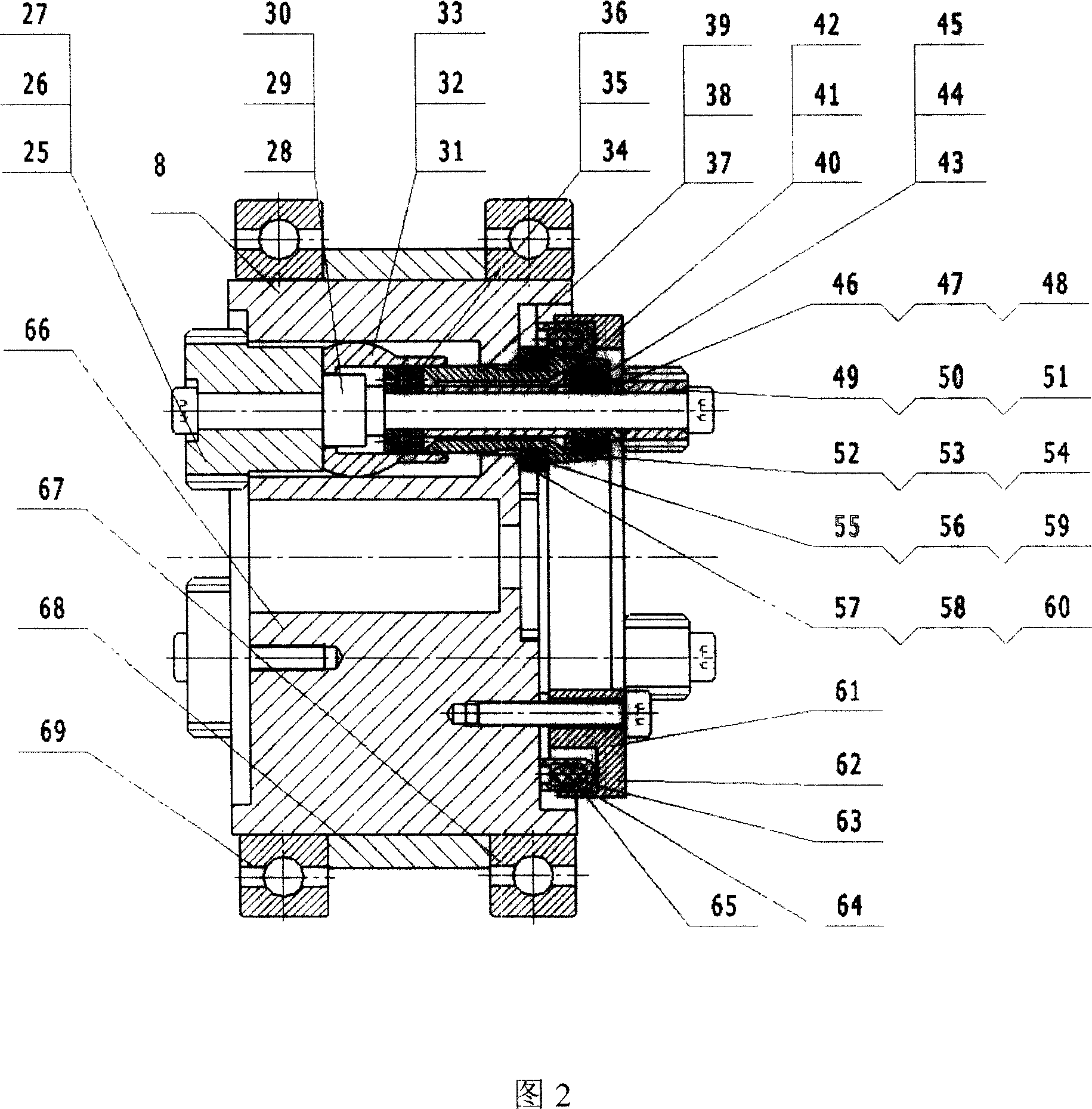
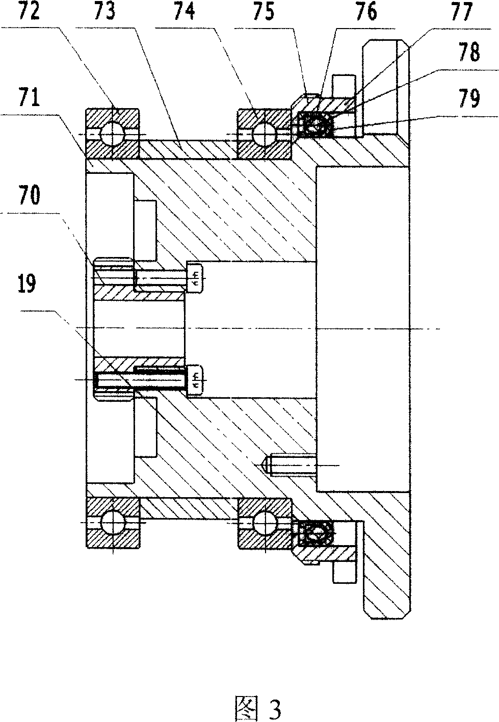
[0015] The present invention will be described in further detail below. 1 and 2, the present invention includes an end cap part 1, a fixed end collimator part 4, an outer casing 25, a gear part 5, an interlocking mechanism assembly 8, a prism mechanism assembly 10, a rotating body assembly 19, and a rotating end collimator assembly. Straightener part 21, corrugated spring 9, connection seat part 20, wherein, prism mechanism assembly 10 comprises prism 11, prism positioning seat 12, spring 13, 14, 15, screw 16, 17, 18, rotating end collimator The positioning part 21 includes a collimator 22, a collimator positioning seat 23, a connecting sleeve 24, an end cover part 20, a fixed end collimator positioning part 4, a gear part 5, a linkage mechanism assembly 8, and a rotating body assembly 19 are fixed on In the outer shell 25, the prism mechanism assembly 10 is fixed in the linkage mechanism assembly 8, the rotating end collimator positioning part 21 is fixed in the rotor assembl...


PUM


Abstract

The invention relates to a fiber rotary connector, which combines optical system and mechanical system to complete optical signal transmission in the relative movement state. Collimator combines the prism to form the fiber rotary connector optical system, and mechanical system uses the planetary gear drive mechanism. The fiber exhaled light passes through the collimator to collimate to big light spot parallel rays, and when the parallel rays rotating with velocity v, the prism rotating with velocity v/2 with the same direction, so the exhaled light and the incident light have the same position. The program features v/2 velocity, and the same direction rotation, so the mechanical system totally uses 8 precision gears, 4 ceramic bearings, 6 double-sealed bearings, and the 8 gears have both rotation and revolution, considering two center round space as multiple planetary transmission loads; the incident parallel rays passes through the optical system, and with the prism all-reflection to form the corresponding exhaled parallel rays. The program can be very convenient to achieve space free rotation, optical signal two-way transmission.

Description

technical field [0001] The invention relates to an optical fiber rotary connector. Background technique [0002] US patent (US5157745) discloses a multi-channel rotary optical fiber connector, which is composed of prisms, bearings, gears, optical fiber alignment mechanisms, rotating shafts, etc. The rotating body is connected to the housing through bearings, and there are prisms at both ends The mechanism realizes the purpose of synchronizing the input and output through the gear transmission mechanism. Due to the complex structure and large size of the optical fiber collimation mechanism, it is difficult to install. Contents of the invention [0003] The object of the present invention is to propose a fiber optic rotary connector with simple structure, small volume and easy installation. The technical solution of the present invention is: an end cover component, a fixed end collimator component, an outer casing, a gear component, a linkage mechanism component, a prism m...

Claims


Application Information

Patent Timeline
IPC IPC(8): G02B6/38G02B6/36G02B27/64
Inventor 程霁竑石素芬陈学永
Owner CHINA AVIATION OPTICAL-ELECTRICAL TECH CO LTD
Why Eureka
Try Eureka