Triangular mechanism for computer flat knitting machine plain flat knitter

A technology of flat knitting machines and guide needle cams, which is applied in knitting, weft knitting, textiles and papermaking, etc. It can solve the problems of strict machining accuracy of needle jacks 17, complex structure of knitting needle components, and increased manufacturing costs, and achieve The head drive is light and flexible, the movement resistance is reduced, and the effect of saving manufacturing costs

Inactive Publication Date: 2007-08-15
JIANGSU JINLONG TECHNOLOGY CO LTD
View PDF2 Cites 16 Cited by
  • Summary
  • Abstract
  • Description
  • Claims
  • Application Information

AI Technical Summary

Problems solved by technology

[0009] It can be seen from the above that, in addition to the very complicated structure of the triangular mechanism itself, the structure of the knitting needle assembly is also complicated. Parts must be used at the same time, and both are indispensable, which brings the following disadvantages: one, the needle bed and the machine head must be kept at a sufficient width, thereby increasing the volume of the complete machine and increasing the manufacturing cost; It can be seen from the principle that whether the knitting needle 16 performs knitting, transfer, tuck, and stitching depends on whether the corresponding push piece 18 is pressed into the needle groove by the non-woven pressing piece 23, the tuck pressing piece 24 or the needle pressing piece 26L, 26R. , when the push piece 18 is pressed into the needle groove, the lower butt 17a of the corresponding needle jack 17 is also pressed into the needle groove, so since the push piece 18 and the needle jack 17 are located in the same needle groove, and the needle jack 17 is below the push piece 18. When the push piece 18 is pressed into the needle groove, it must first overcome the elastic tension of the needle jack 17. Only by forcing the needle jack 17 to bend down can the lower butt 17a sink into the needle groove. When the external force is eliminated, the lower butt 17a pops out of the needle groove again, so the resistance when the push piece 18 is pressed into the needle groove is relatively large, and the driving power of the machine head is correspondingly required to be relatively large, and when the push piece 18 is pressed into the needle groove , the non-woven pressing piece 23, the tuck pressing piece 24 or the needle pressing piece 26L, 26R are easy to wear; three, because the lower butt 17a of the needle jack 17 is always close to the needle lifting triangle 5 and along the needle bevel 5a Or 5b rises, so the machining accuracy of the needle jack 17 is very strict, otherwise it will cause the needle

Method used


Image

  • Triangular mechanism for computer flat knitting machine plain flat knitter
  • Triangular mechanism for computer flat knitting machine plain flat knitter
  • Triangular mechanism for computer flat knitting machine plain flat knitter

Examples


Embodiment Construction

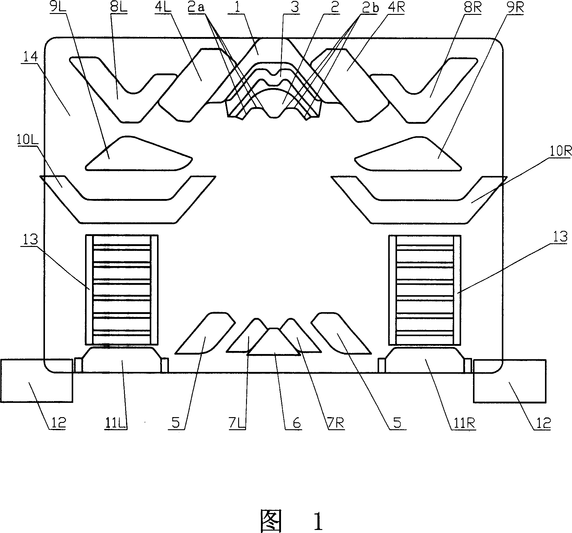
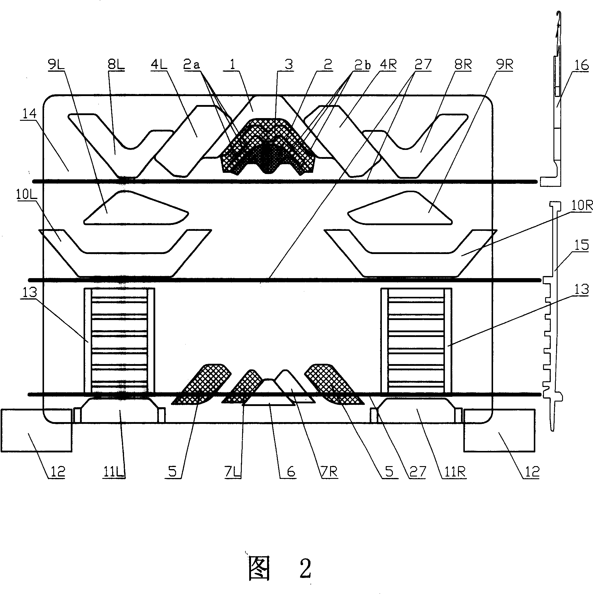
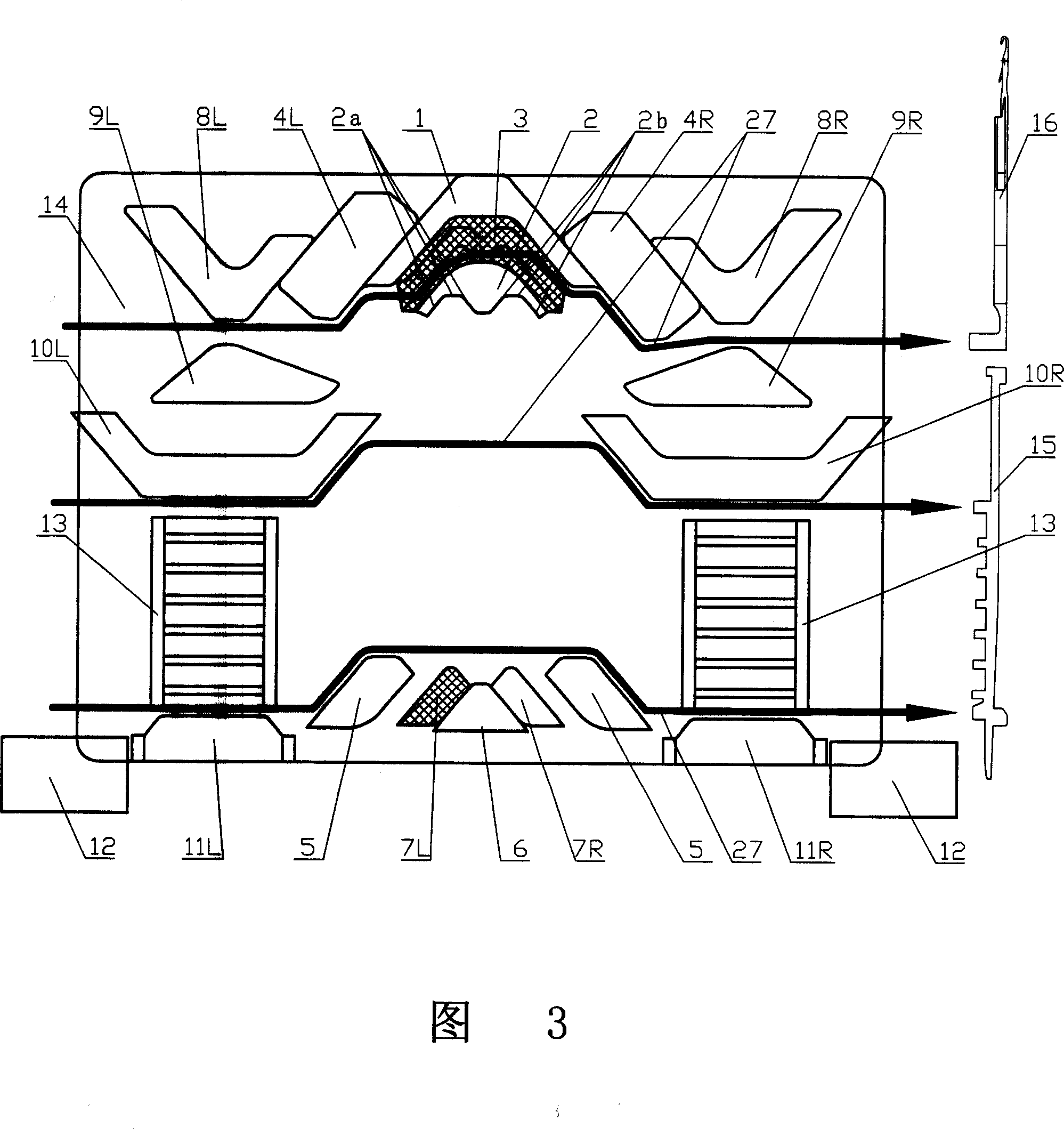
[0032]See also Fig. 1, have provided a rectangle and have triangular bottom plate 14, and it is installed on the machine head of computer knitting flat knitting machine, and it has a pair of front and rear sides that are respectively installed in machine head, thereby on the left side of machine head , Right reciprocating row moves down and drives the knitting needle work of the knitting needle assembly that is positioned at needle plate or claims the needle bed. Taking the position shown in the figure as an example, a pair of generally V-shaped guide pin cams 8L and 8R are respectively fixed with screws on two sides of the upper part of the triangular bottom plate 14, and L and R appearing here represent left and right respectively. (The same below). A pair of guide pin cams 9L, 9R are respectively fixed with screws below the corresponding guide pin cams 8L, 8R, and a pair of guide pin cams are respectively fixed with screws at the lateral near-middle part of the triangular b...


PUM


Abstract

A triangle device of computer knitting machine comprises a triangle bottom plate, and a needle triangle, a couple of needle selecting pin return triangles, and a couple of needle selectors which are respectively fixed on the triangle bottom plate, and a needle triangle, a turnover triangle, and a couple of needle selecting triangles respectively arranged on the triangle bottom plate, and a couple of density triangles on the triangle bottom plate. The invention is characterized in that the invention also comprises a herring triangle, a raising triangle and a couple of needle collecting triangles, wherein the herring triangle and the raising triangle are respectively fixed on upper and lower parts of the triangle bottom plate and at the middle, the needle collecting triangles are contacted at two sides of the raising triangle. The invention has the advantages that the inventive triangle device has simple structure, easy installment, and small volume or the like, while the operation resistance of knitting needle is reduced significantly and the machine head is driven flexibly, with low driving power and low cost.

Description

technical field [0001] The present invention relates to a computerized flat knitting machine, and more specifically relates to a triangle mechanism of a computerized flat knitting machine suitable for the action of six-section needle selection feet on high and low butt knitting needles. Background technique [0002] The cam mechanism of the computerized flat knitting machine in the prior art is shown in Fig. 10, which mainly includes a cam base plate 14, a starting cam 5 fixed on the cam base plate 14, a transfer guide cam 20, and a guide cam 8L respectively. . Sliding density cams 4L, 4R, stitch selection reset cams 12 and needle selectors 13 fixed on the triangular bottom plate 14, needle pushing cams 21L, 21R, needle clearing cams 22L, 22R, the non-woven pressing piece 23 fixed on the triangular bottom plate 14 protrudes from the triangular bottom plate 14 and the swingable tuck pressing piece 24, the second-stage stitch pressing piece 25L, 25, 25R can be placed vertical...

Claims


Application Information

Patent Timeline
Patent Type & Authority Applications(China)
IPC IPC(8): D04B15/36
Inventor 金永良付洪平
Owner JIANGSU JINLONG TECHNOLOGY CO LTD
Why Eureka
Try Eureka