
Heat resistance network model and method for calculating junction temperature of microelectronics using same

A technology for microelectronic devices and network models, which is applied in computing, instrumentation, electrical digital data processing, etc., and can solve problems such as poor thermal resistance prediction accuracy of simple thermal model

Active Publication Date: 2007-08-15
CHINA ELECTRONICS PROD RELIABILITY & ENVIRONMENTAL TESTING RES INST
View PDF0 Cites 22 Cited by
  • Summary
  • Abstract
  • Description
  • Claims
  • Application Information

AI Technical Summary

Problems solved by technology

[0005] In view of the shortcomings of the prior art, the purpose of the present invention is to provide a thermal resistance network model and a method for calculating the junction temperature of microelectronic devices using the model, so as to solve the problem of traditional thermal resistance changing with boundary changes and poor prediction accuracy of the junction temperature of the simple thermal model lack of

Method used


Image

  • Heat resistance network model and method for calculating junction temperature of microelectronics using same
  • Heat resistance network model and method for calculating junction temperature of microelectronics using same
  • Heat resistance network model and method for calculating junction temperature of microelectronics using same

Examples


Embodiment Construction

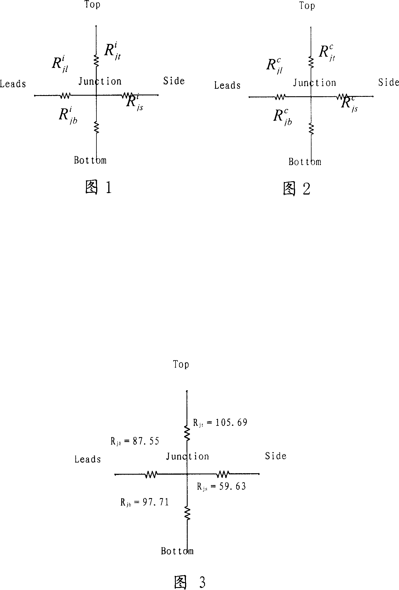
[0027] Please refer to Fig. 1 and Fig. 2, the thermal resistance network of the present invention adopts star structure representation, constitutes with the four nodes that represent top surface, side, bottom surface and pin that are connected with junction, pass branch road between each node and junction The thermal resistances are connected, and the thermal resistances of each branch respectively represent the effect of the top surface, side surface, bottom surface and pins on the heat dissipation of the device. The intrinsic thermal resistance network and the nominal thermal resistance network use the same structure, the intrinsic thermal resistance network is used for isothermal boundary conditions, and the nominal thermal resistance network is used for convective boundary conditions.

[0028] The following is the modeling and junction temperature calculation process of microelectronic devices:

[0029] (1) Improve the existing definition of thermal resistance, and propose...


PUM


Abstract

This invention discloses one thermal resistant network module and discloses one method to computer micro electron part by use of thermal resistance network, which comprises the following steps: according to the resistance network module to get unknown parameters temperature expression; processing thermal test to get micro electron part relative temperature data; extracting micro electron part parameters; establishing electron part limit element artificial module; correcting the limit module to ensure limit module accuracy to get effect module for limit artificial data; establishing optimization function to process optimization process to determine the unknown parameters value to get each boundary condition temperature.

Description

technical field [0001] The invention relates to thermal reliability technology of microelectronic packaging, in particular to a thermal resistance network model and a method for calculating junction temperature of microelectronic devices using the model. Background technique [0002] For a long time, there is no effective and convenient method for engineering and technical personnel to conveniently calculate the junction temperature of microelectronic devices in the actual working environment to ensure that the operating temperature of the device chip does not exceed the maximum allowable junction temperature, and due to the lack of standard IC thermal models , also brings difficulties to accurate thermal design. With the increasing miniaturization and high assembly density of microelectronic packaging, the heat flux density of microelectronic packaging is increasing, and the problem of thermal reliability is becoming more and more prominent. [0003] At present, general us...

Claims


Application Information

Patent Timeline
Patent Type & Authority Applications(China)
IPC IPC(8): G06F17/50
Inventor 邱宝军蒋明何小琦杨邦朝
Owner CHINA ELECTRONICS PROD RELIABILITY & ENVIRONMENTAL TESTING RES INST
Learn More