Superconducting magnet apparatus and nuclear magnetic resonance imaging apparatus
A technology of superconducting magnets and magnetic fields, applied in the direction of superconducting magnets/coils, measuring devices, magnetic objects, etc., can solve the problems of increased number of parts, increased space size, increased weight, etc., to achieve suppression of deformation, suppression of total weight, The effect of stabilizing the magnetic field for high-precision measurement
- Summary
- Abstract
- Description
- Claims
- Application Information
AI Technical Summary
Problems solved by technology
Method used
Image
Examples
no. 1 approach
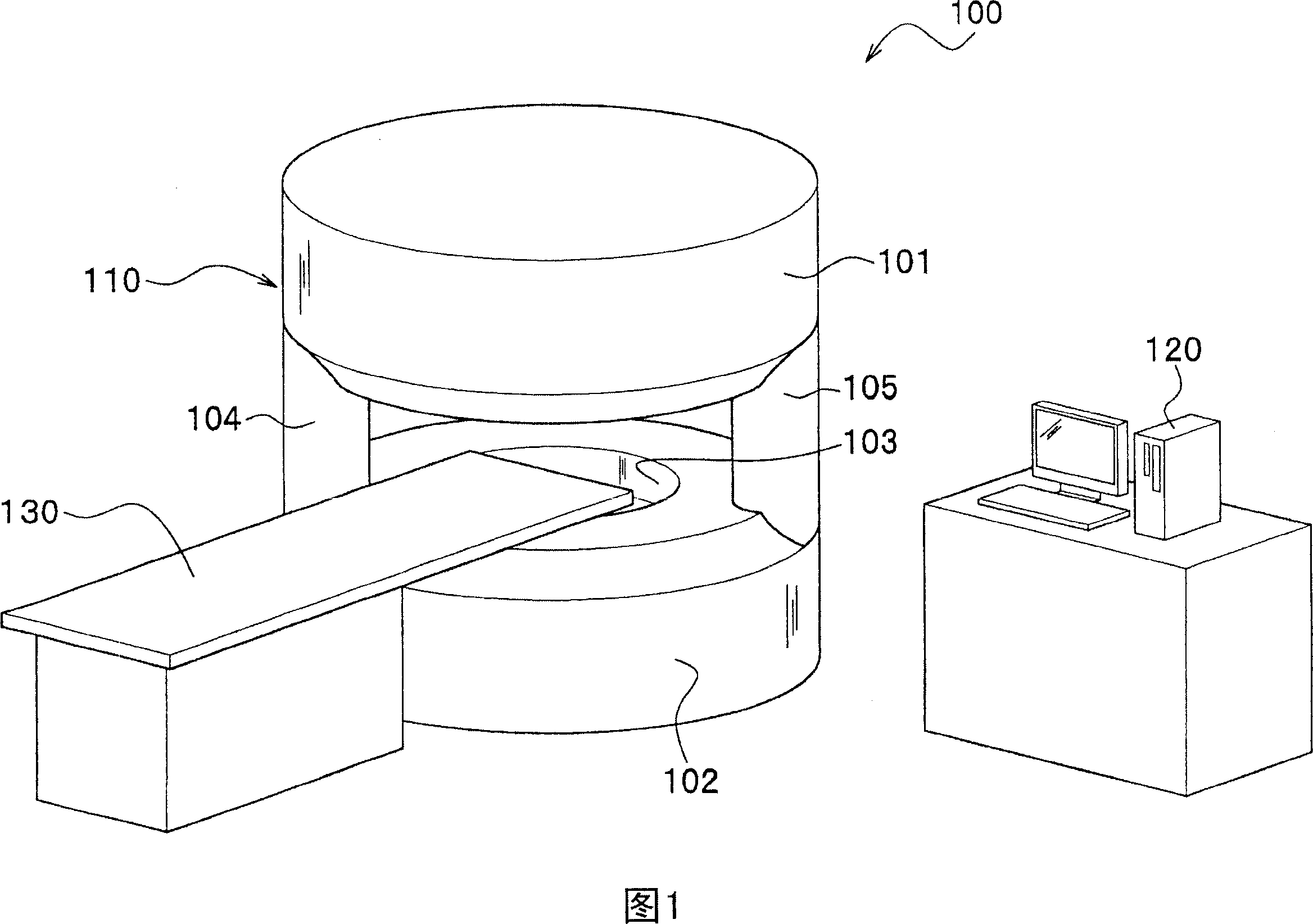
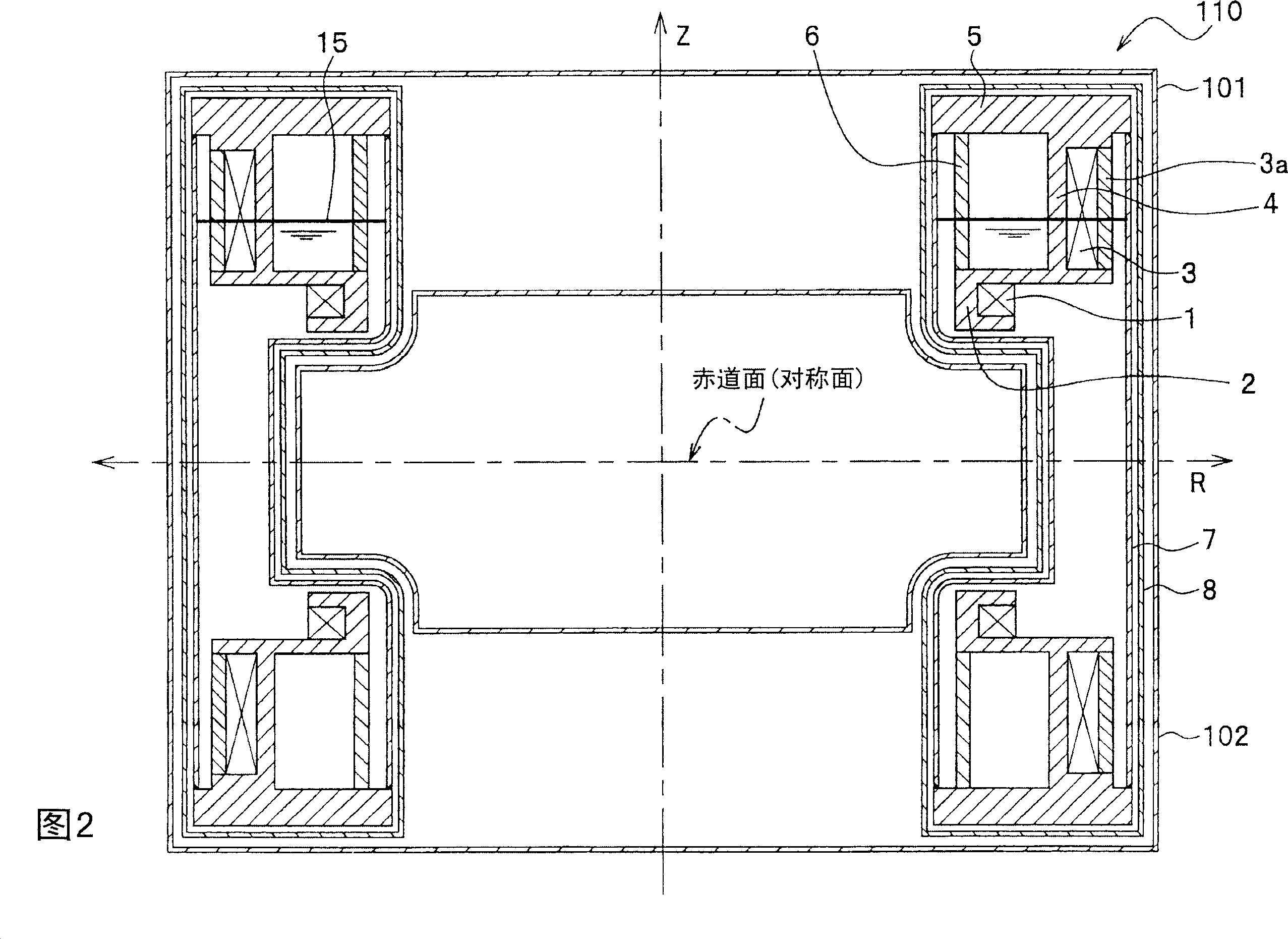
[0026] FIG. 1 is a diagram showing a schematic configuration example of an MRI apparatus using a superconducting magnet apparatus according to an embodiment of the present invention. Moreover, FIG. 2 is a view showing a vertical cross-section of the superconducting magnet device including the pillar portion of the MRI device in FIG. 1 .
[0027] As shown in FIG. 1, in the MRI apparatus 100, two cylindrical vacuum containers 101, 102 are spaced up and down between each other and arranged approximately symmetrically. Support and connect. A portion sandwiched between the two cylindrical vacuum containers 101 and 102 is a measurement space formed by the MRI apparatus 100 , and the front end portion of a bed 130 on which a patient or the like to be tested is placed can enter and exit the measurement space.
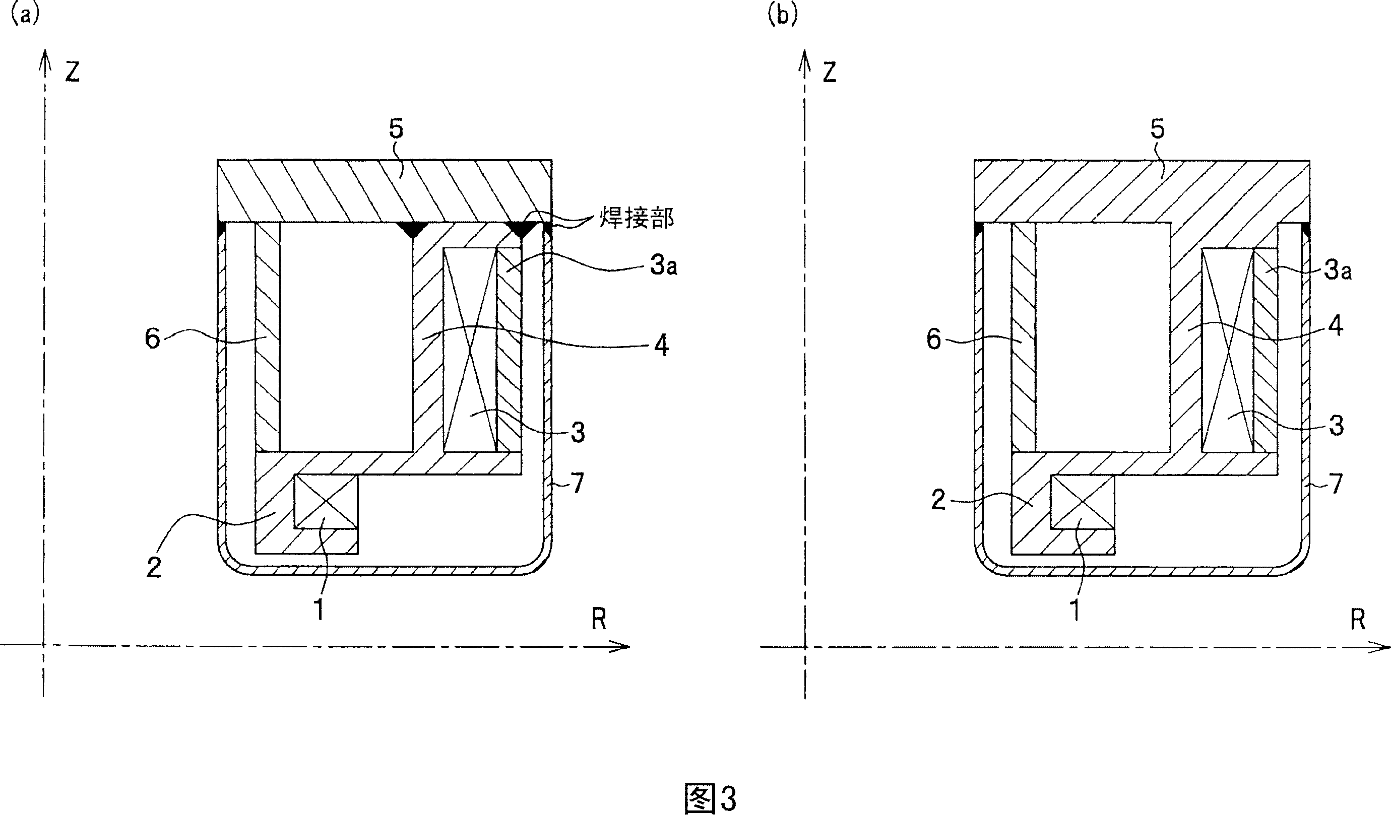
[0028] The insides of the vacuum containers 101 and 102 are kept in a vacuum to prevent the intrusion of heat by conduction and convection. And, as shown in FIG. 2 , inside i...
no. 2 approach
[0041] 4 is a diagram showing an example of a cross-sectional structure when an annular helium container according to a second embodiment of the present invention is cut on a plane perpendicular to the circumferential direction. In addition, in the second embodiment, the basic configurations of the superconducting magnet device 110 and the MRI device 100 are the same as those of the first embodiment. Therefore, in the following description, the same components as in the case of the first embodiment are assigned the same symbols, and descriptions thereof are omitted (the same applies to the following embodiments as well).
[0042] As shown in FIG. 4 , in this embodiment, the shield bobbin 4 is formed integrally with the thick plate 5 by casting or the like, but the main bobbin 2 is formed separately. Furthermore, the main bobbin 2 is connected to the shield bobbin 4 by means of fixing metal fittings 10 etc. which are bolted, and further, is attached to the thick plate 5 via the...
no. 3 approach
[0047] 5 is a diagram showing an example of the internal structure of an annular helium container according to a third embodiment of the present invention, (a) is an example of a cross-sectional structure when the annular helium container is cut on a plane perpendicular to the circumferential direction, ( b) is a perspective view when a shield bobbin and a main bobbin are disassembled, and a perspective view after connecting them. In addition, in FIG. 5( b ), the uppermost figure is a figure showing the shield bobbin 4 , and the middle figure is a figure showing the main bobbin 2 . In addition, the figure of the lowest layer is a figure which shows the main bobbin 2 and the shield bobbin 4 after connection.
[0048] In this embodiment, as shown in FIGS. 5( a ) and ( b ), a plurality of (for example, six) protrusions 2 a are formed at predetermined intervals in the circumferential direction on the outer periphery of the main bobbin 2 . In addition, on the surface of the equato...
PUM
 Abstract
Description
Claims
Application Information
 - R&D
- Intellectual Property
- Life Sciences
- Materials
- Tech Scout
- Unparalleled Data Quality
- Higher Quality Content
- 60% Fewer Hallucinations
Browse by: Latest US Patents, China's latest patents, Technical Efficacy Thesaurus, Application Domain, Technology Topic, Popular Technical Reports.
© 2025 PatSnap. All rights reserved.Legal|Privacy policy|Modern Slavery Act Transparency Statement|Sitemap|About US| Contact US: help@patsnap.com


