Optical fiber automatic monitoring system and method

An automatic monitoring and optical fiber technology, applied in transmission systems, electromagnetic wave transmission systems, electrical components, etc., can solve the problems of short service life and poor real-time performance of system equipment, and achieve real-time monitoring, enhanced real-time performance, and extended equipment life.

Inactive Publication Date: 2007-08-15
HUAWEI TECH CO LTD
View PDF0 Cites 25 Cited by
  • Summary
  • Abstract
  • Description
  • Claims
  • Application Information

AI Technical Summary

Problems solved by technology

[0010] In view of this, the present invention provides an optical fiber automatic monitoring system and method, which improves the shortcomings of tr

Method used


Image

  • Optical fiber automatic monitoring system and method
  • Optical fiber automatic monitoring system and method
  • Optical fiber automatic monitoring system and method

Examples


Example Embodiment

[0056] The present invention is an optical fiber automatic monitoring system and method. In order to make the purpose, technical solution and advantages of the present invention clearer, the following describes the present invention in detail with reference to the accompanying drawings and examples.

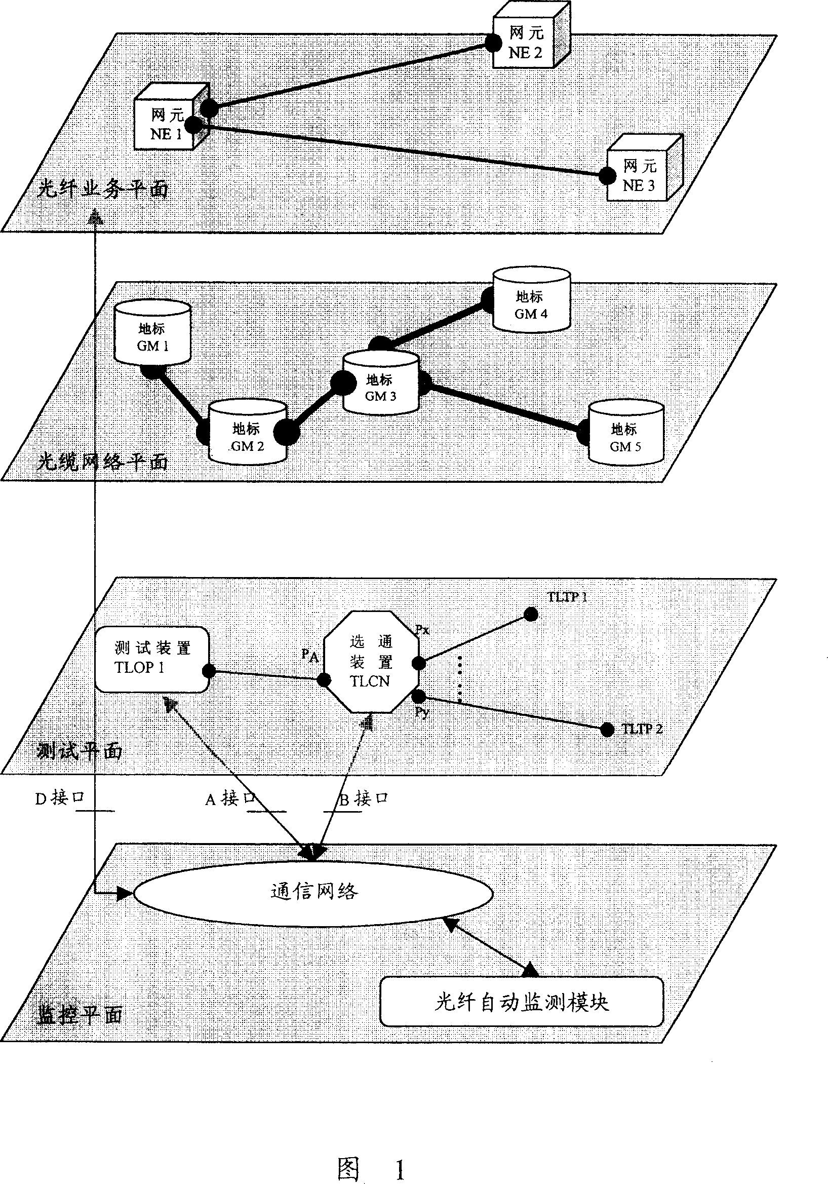
[0057] Referring to Fig. 1, the system provided by the present invention mainly includes: an optical cable network plane, an optical fiber service plane, a test plane and a monitoring plane.

[0058] Among them, the optical cable network plane includes optical cable segments, which are used to provide access to the physical medium layer for the optical fiber service plane and test plane;

[0059] The optical fiber service plane includes network element equipment, which is used to generate abnormal events that trigger system tests and report the abnormal events to the monitoring plane;

[0060] The test plane is used to test the test link and report the test results to the monitor...


PUM


Abstract

The disclosed fiber automatic monitor system comprises: a fiber network profile, an optical business profile to generate abnormal affair to trigger system testing, a detection profile, and a monitor profile to control the detection and thereby find out the fault position. This invention improves performance traditional technology obviously, and has better performance on real time and system service time.

Description

technical field [0001] The invention relates to the field of optical fiber communication, in particular to an optical fiber automatic monitoring system and method. Background technique [0002] In recent years, with the continuous improvement of the demand for broadband services, optical fiber communication has been vigorously developed due to its many advantages. But at the same time, the maintenance problems of optical cables are becoming more and more prominent. Therefore, it is very important to implement real-time monitoring of optical cable lines. [0003] The optical fiber automatic monitoring system uses the remote test of the optical fiber backscattering curve to realize the automatic monitoring of the optical cable line. Domain Reflectometer (Optical Time Domain Reflectometer, OTDR) device is tested to determine the location of the cable fault. The primary problem in realizing this function is how to detect the abnormality of the optical cable in time, determine ...

Claims


Application Information

Patent Timeline
IPC IPC(8): H04B10/08H04B10/12H04B10/077
Inventor 潘旭辉
Owner HUAWEI TECH CO LTD
Why Eureka
Try Eureka