Sensing apparatus and method
A sensor and intermediate coupling technology, applied in the direction of measuring devices, converting sensor output, using electric/magnetic devices to transfer sensing components, etc., can solve problems such as influence
- Summary
- Abstract
- Description
- Claims
- Application Information
AI Technical Summary
Problems solved by technology
Method used
Image
Examples
no. 1 example
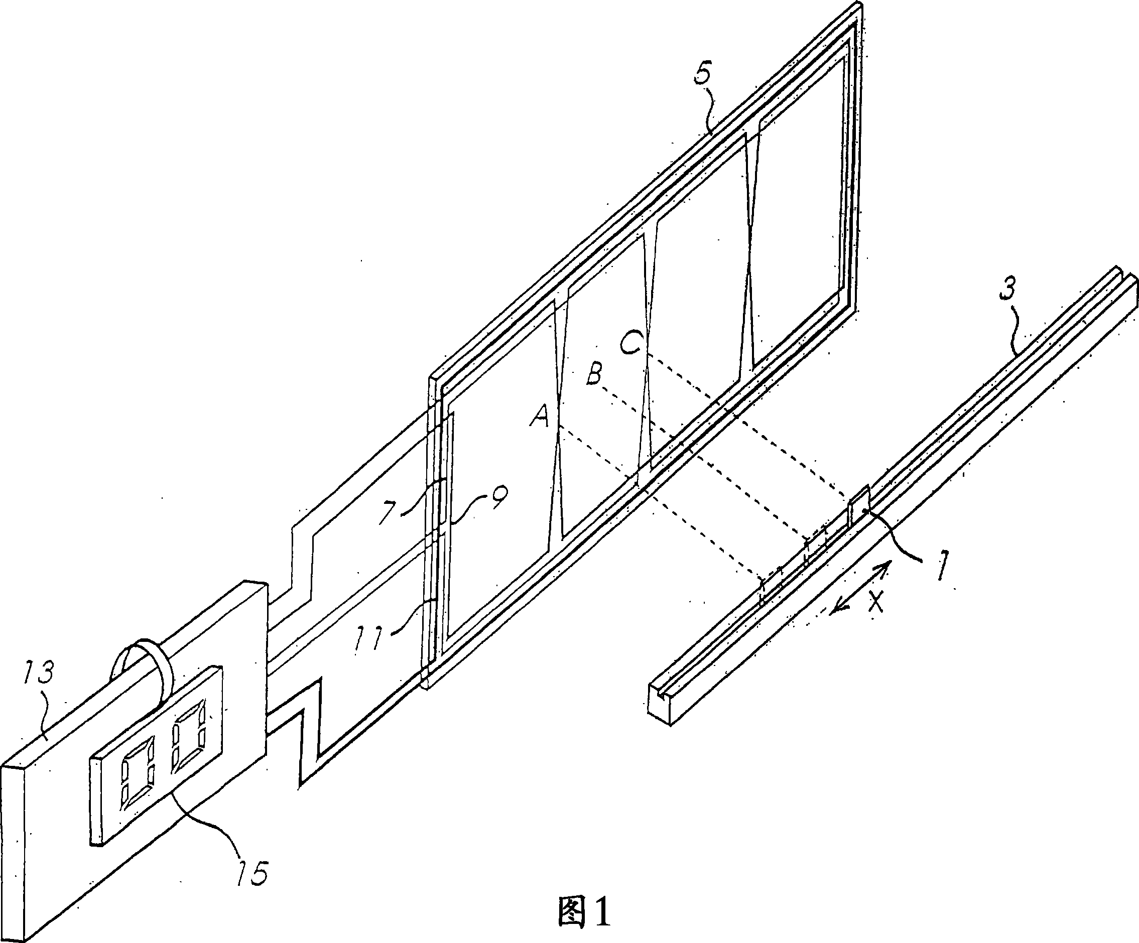
[0027] Figure 1 exemplarily shows a position sensor for detecting the position of a sensor element 1 which is slidably mounted on a support 3 to allow a linear movement in the measuring direction (direction X in Figure 1) . A printed circuit board (PCB) 5 extends in the direction of measurement adjacent to the support 3 and has printed on it conductive paths forming a sine winding 7, a cosine winding 9 and a sensing winding 11, which are all connected to the control Unit 13. A display 15 is also connected to the control unit 13 for displaying numbers representing the position of the sensing element 1 along the support 3 .
[0028] The layout of the sinusoidal winding 7 is such that the current flowing through the sinusoidal winding 7 generates a magnetic field component B perpendicular to the PCB 5 1 The first magnetic field of , which varies along the measurement direction according to one period of the sinusoidal function over the distance L. Similarly, the layout of the ...
no. 2 example
[0048] In a first embodiment, the intermediate coupling element is formed by a winding in parallel with a diode. A second embodiment will now be described with reference to FIG. 8, in which the intermediate coupling element of the first embodiment is replaced by an intermediate coupling element having low impedance characteristics. The remaining components of the second embodiment are the same as the corresponding components of the first embodiment.
[0049] As shown in FIG. 8 , in this embodiment, the intermediate coupling element is formed by a winding 31 , a diode 33 and a capacitor 101 all connected in parallel. The parallel connection of winding 31 with associated inductance and capacitor 101 forms a circuit where the reactance of capacitor 101 effectively cancels the reactance of winding 31 at a certain frequency (hereinafter referred to as the low impedance frequency). In this embodiment, the inductance of the winding 31 and the capacitance of the capacitor 101 are set...
no. 3 example
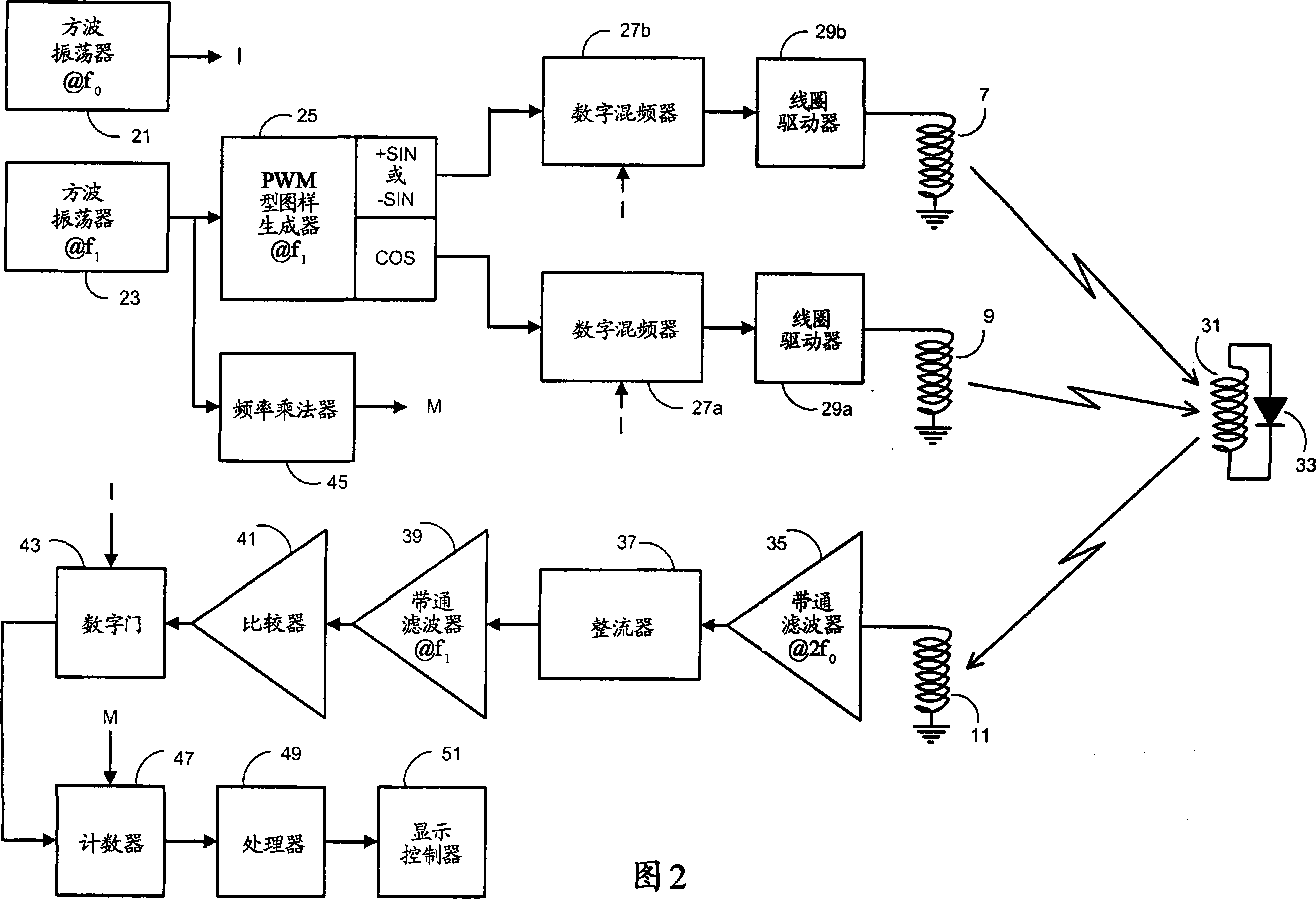
[0052] In a first embodiment, the winding 31 in the intermediate coupling element is coupled to both the transmit and receive antennas. Since the signal processing circuit uses a carrier frequency f 0 To determine a value representing the position of the sensor element 1 relative to the PCB 5, a signal around the second harmonic of , it is therefore desirable to reduce the value at the carrier frequency f 0 The coupling of the signal to the sensor winding 11.
[0053] A third embodiment is now described with reference to FIGS. 9 and 10 , wherein the layout of the sine winding 7, cosine winding 9 and sensor winding 11 in the first embodiment is changed, and the intermediate coupling element of the first embodiment is replaced by an intermediate coupling component replaced.
[0054] As shown in FIG. 9 , in this embodiment, the intermediate coupling element has an input winding 111 and an output winding 113 . The diode 115 is connected between one end of the input winding 111 ...
PUM
 Abstract
Description
Claims
Application Information
 - R&D
- Intellectual Property
- Life Sciences
- Materials
- Tech Scout
- Unparalleled Data Quality
- Higher Quality Content
- 60% Fewer Hallucinations
Browse by: Latest US Patents, China's latest patents, Technical Efficacy Thesaurus, Application Domain, Technology Topic, Popular Technical Reports.
© 2025 PatSnap. All rights reserved.Legal|Privacy policy|Modern Slavery Act Transparency Statement|Sitemap|About US| Contact US: help@patsnap.com


