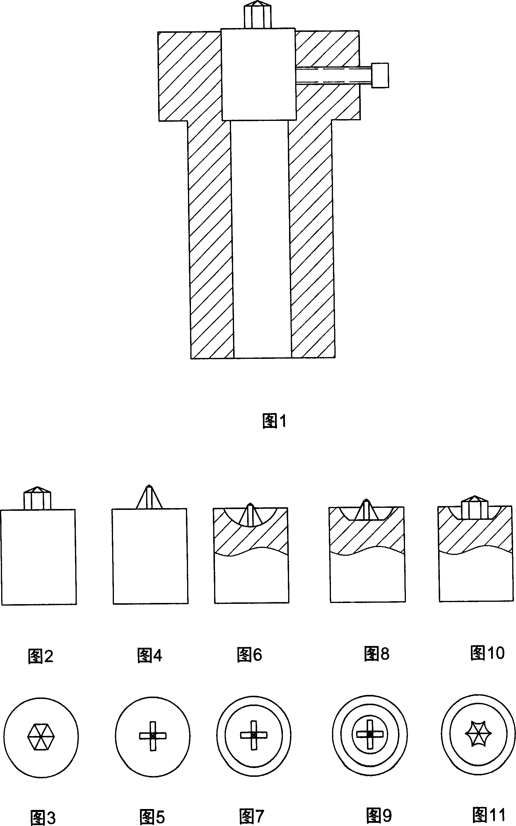
Screwhead punching pin locking method and screwhead punching die
A technology for screwdrivers and screw heads, which is applied in the fields of locking screwdriver groove punching heads of screw heads and punching molds, can solve the problems of waste and large waste, achieve long service life, convenient disassembly, and save production preparation time Effect
- Summary
- Abstract
- Description
- Claims
- Application Information
AI Technical Summary
Problems solved by technology
Method used
Image
Examples
Embodiment 1
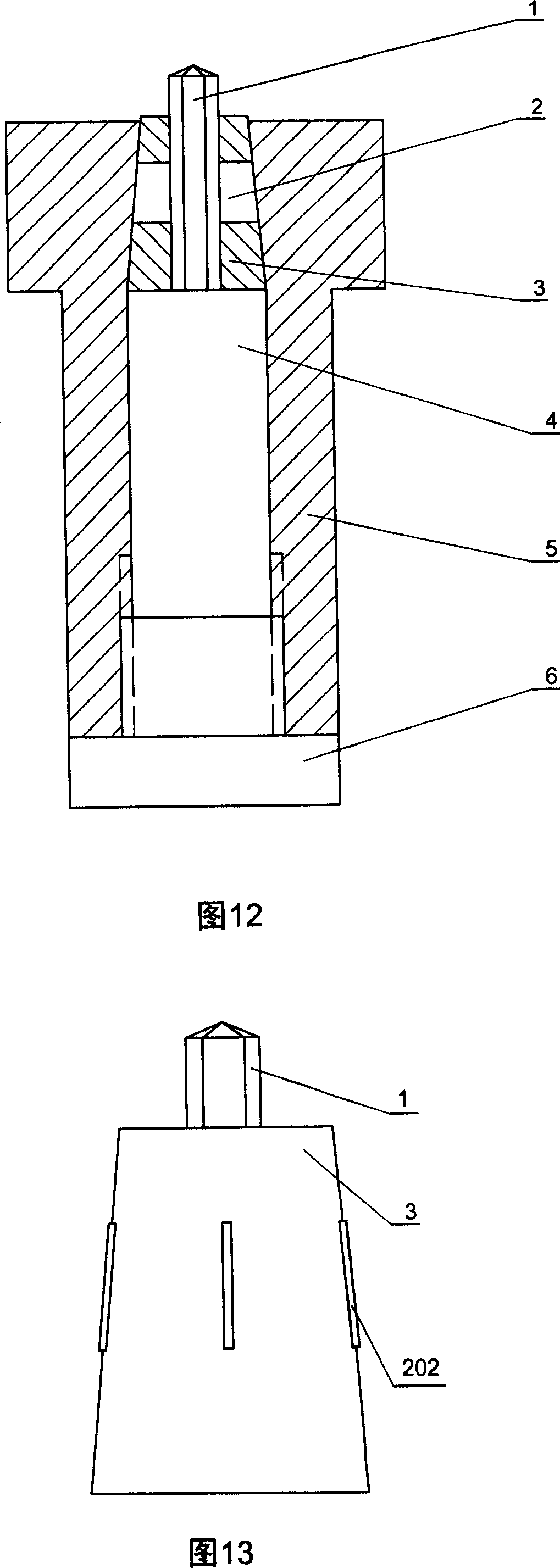
[0029] Fig. 12 is a schematic diagram of the principle of this embodiment. This embodiment includes: a screwdriver groove punching head 1, the screwdriver groove punching head is a cylindrical body with the same size up and down. A cylindrical punch cover 5 with an inner conical surface, a frustum-shaped punch seat 3 with a hole in the center, a cushion block 4, and a cover seat 6 threaded with the punch cover. The conical angle of the outer conical surface of the frustum-shaped punch seat is equal to the inner conical angle of the punch sleeve, and the hole in the middle can be circular or other shapes, usually a shape that conforms to the cross-section of the punching head. For example, if the cross-sectional shape of the punching head is a hexagonal prism, the shape of the center hole of the punch sleeve is also a hexagonal prism, as shown in Figure 27; if the cross-sectional shape of the punching head is a cross, the shape of the center hole of the punch sleeve is also a c...
Embodiment 2
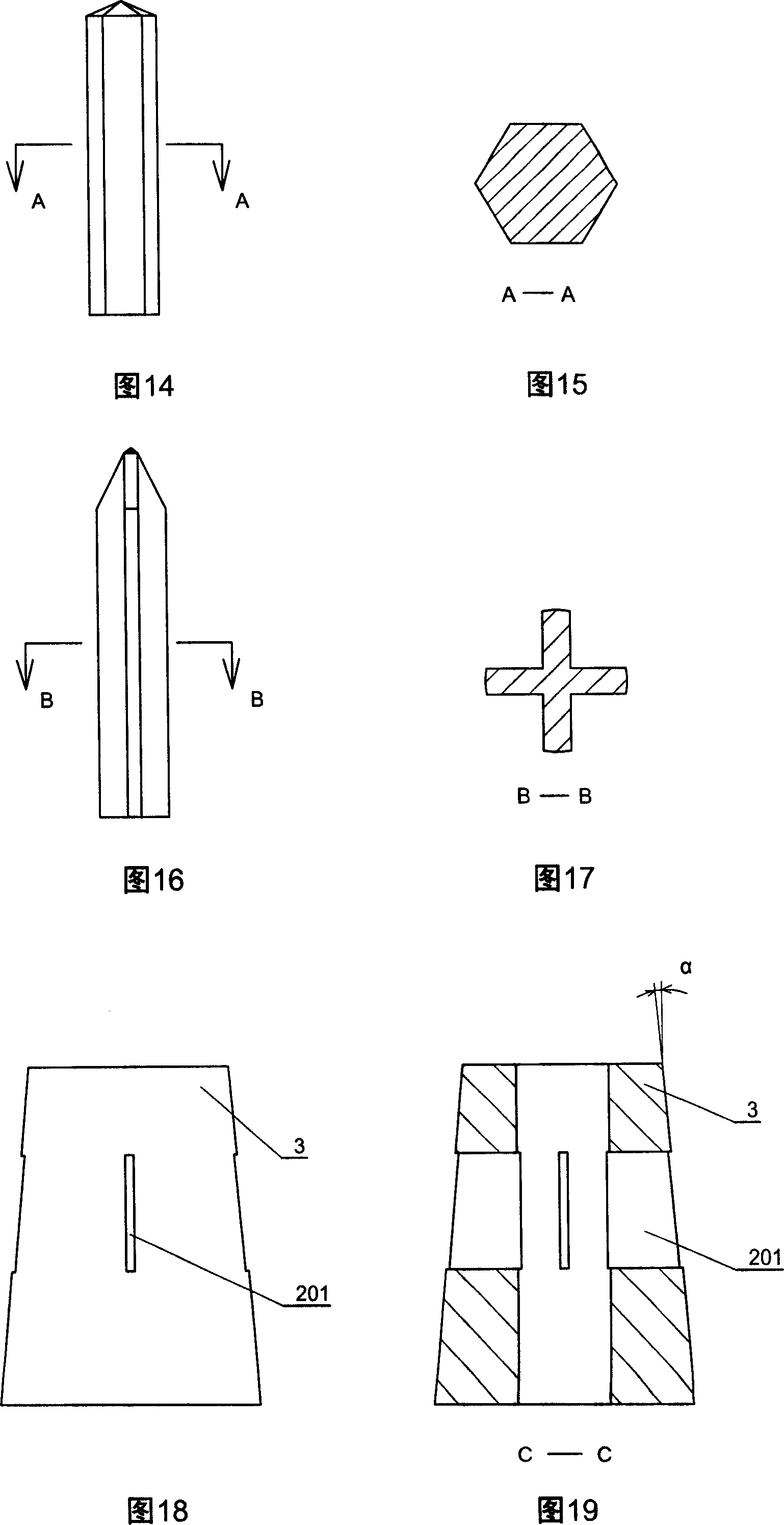
[0032] Fig. 12 is a schematic diagram of the assembly of this embodiment. The screwdriver groove punching head 1 is a rod-shaped cylinder with the same size up and down except for the punching cone at the top, as shown in Figs. 14-17. That is to say, what is the shape of the screwdriver groove to be punched, and what is the shape of the rod-shaped column of the punching head of the screwdriver groove. For example, if the screwdriver groove is cross-shaped, then the rod-shaped cylinder of the screwdriver groove punching head is cross-shaped, as shown in Figures 16-17; if the screwdriver groove is hexagonal, the rod-shaped cylinder of the screwdriver groove punching head The cylinder is exactly hexagonal, as shown in Figures 14-15, and so on. The purpose of this design is to reuse the rod-shaped cylinder of the screwdriver groove punching head. Once the front end is worn, the worn part can be worn away by grinding. When installing, as long as some small pads are placed at the r...
Embodiment 3
[0040] Other aspects of this embodiment are the same as that of Embodiment 1, except that the locking block 202 of the locking device used in this embodiment is cylindrical, and the corresponding locking hole 201 on the punch seat is also circular. hole, as shown in Figure 22-25. The two ends of the cylinder are not parallel and have an included angle α, as shown in Figure 25. The advantage of this embodiment is that the processing is more convenient and the manufacturability is better. The locking block of the locking device can also have other forms. Such as square or rhombus etc.
PUM
 Abstract
Description
Claims
Application Information
 - R&D
- Intellectual Property
- Life Sciences
- Materials
- Tech Scout
- Unparalleled Data Quality
- Higher Quality Content
- 60% Fewer Hallucinations
Browse by: Latest US Patents, China's latest patents, Technical Efficacy Thesaurus, Application Domain, Technology Topic, Popular Technical Reports.
© 2025 PatSnap. All rights reserved.Legal|Privacy policy|Modern Slavery Act Transparency Statement|Sitemap|About US| Contact US: help@patsnap.com


