Supercharge Your Innovation With Domain-Expert AI Agents!

Friction roller type controllable sliding oil-saving clutch

A sliding device and clutch technology, which is applied in the direction of friction clutches, clutches, one-way clutches, etc., and can solve problems such as vehicle forward and backward, joints are not smooth, and gears cannot be shifted.

Inactive Publication Date: 2007-08-22
张恩 +1
View PDF0 Cites 31 Cited by
  • Summary
  • Abstract
  • Description
  • Claims
  • Application Information

AI Technical Summary

Problems solved by technology

When the coasting speed is reduced to a certain appropriate speed, the engine must be driven to increase the speed, and the clutch must be re-engaged after changing gears or not changing gears. There will be a large speed difference between them, which will accelerate the wear of the clutch friction plate, the pressure plate and the friction surface of the flywheel
Moreover, the combination will be uneven, causing the vehicle to rush forward and sit backwards, and even fail to shift gears.
At the same time, because the clutch is disengaged for a long time during coasting, the wear of the release bearing will be accelerated.

Method used


Image

  • Friction roller type controllable sliding oil-saving clutch
  • Friction roller type controllable sliding oil-saving clutch
  • Friction roller type controllable sliding oil-saving clutch

Examples


Embodiment Construction

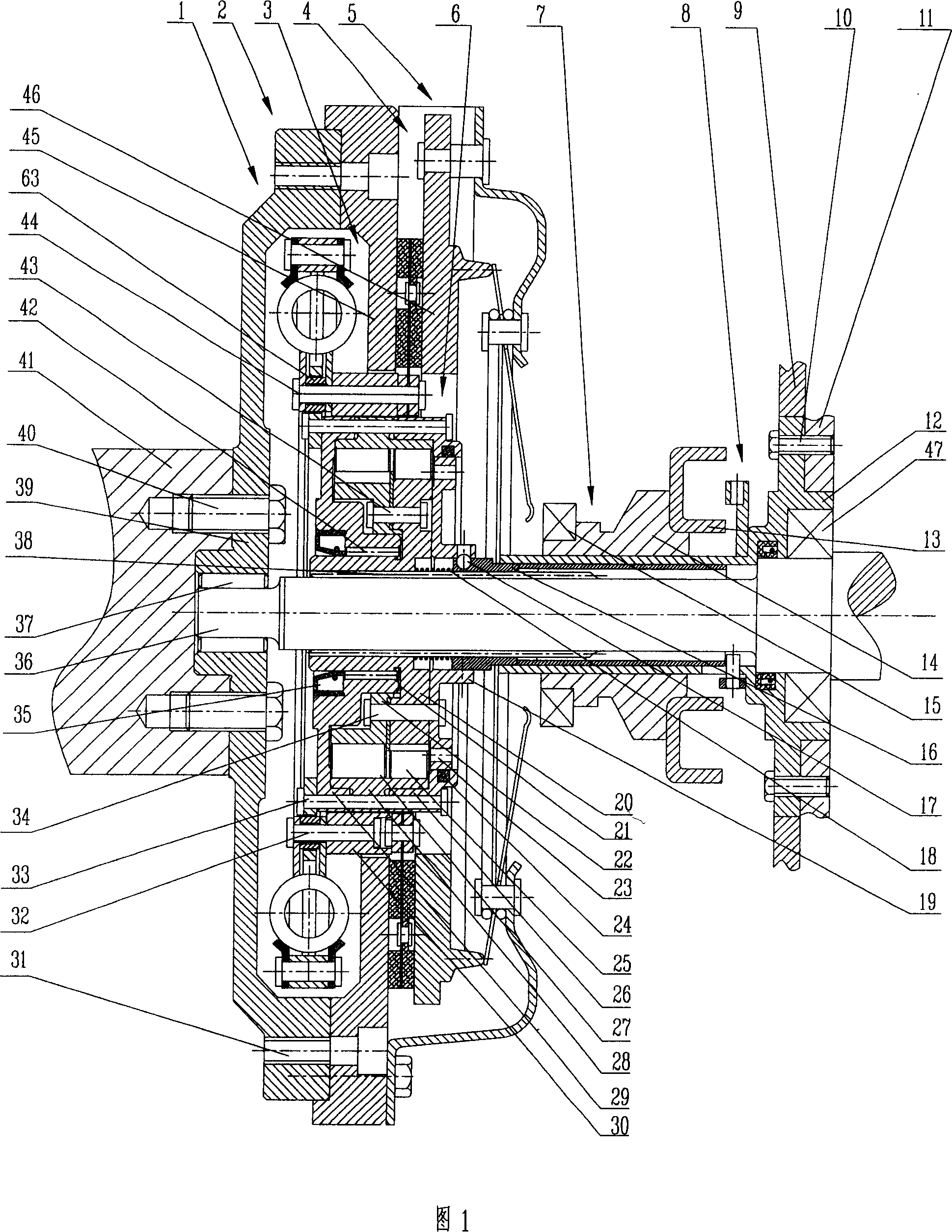
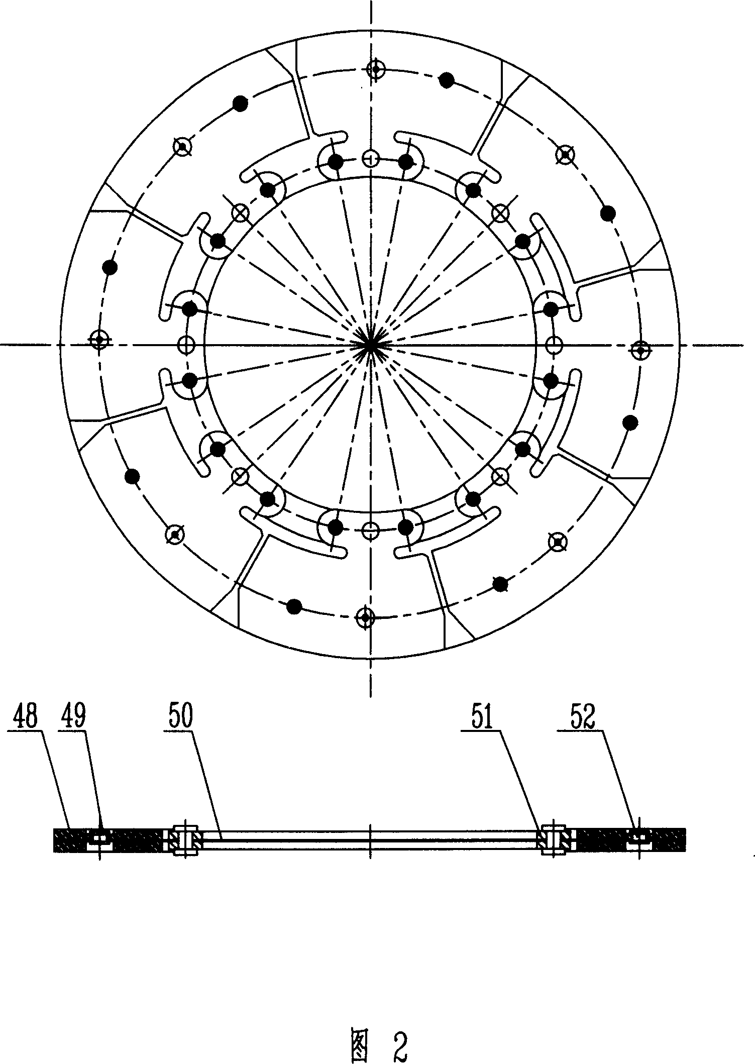
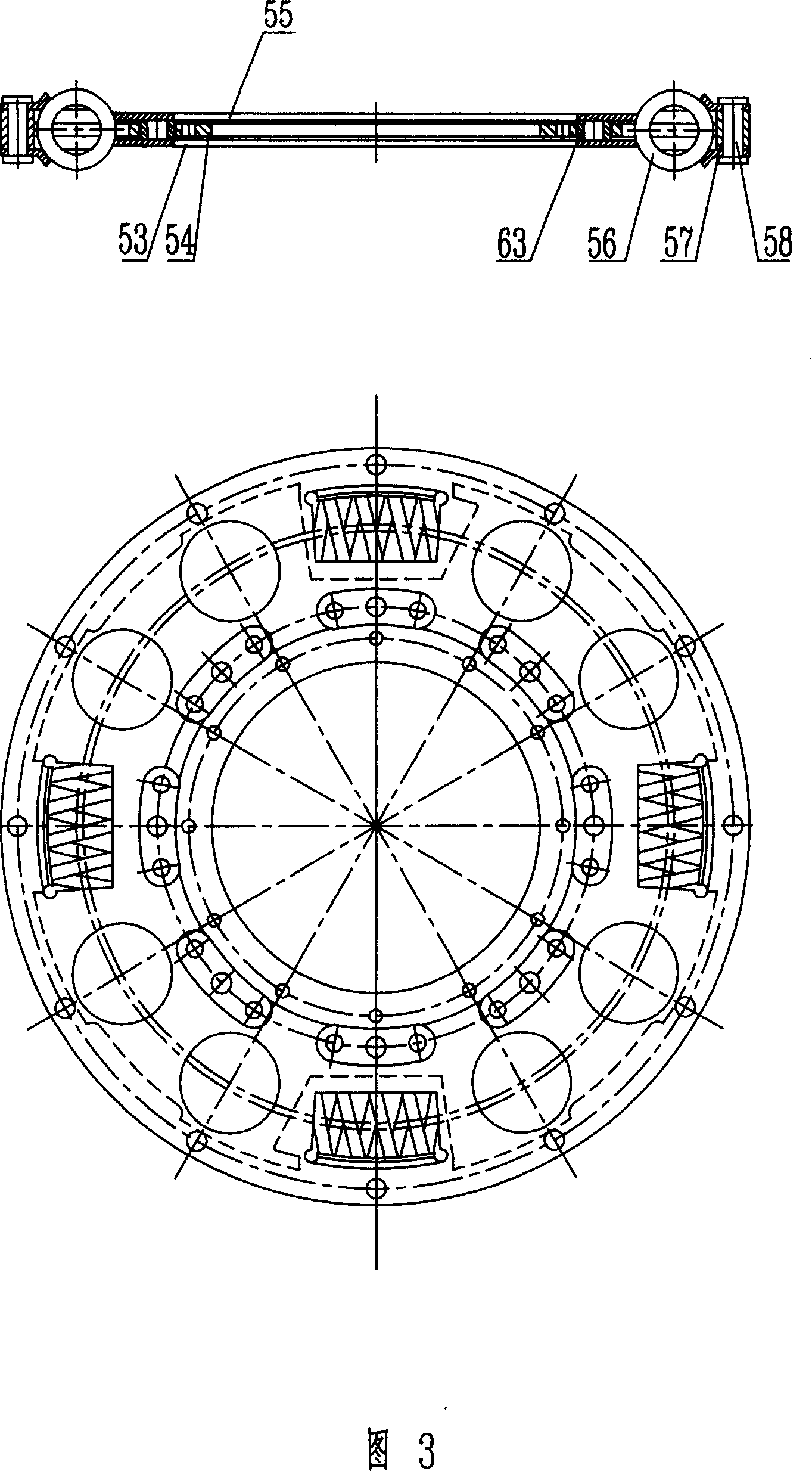
[0014] Embodiments of the present invention are described below according to the accompanying drawings. In this description, "front" refers to the side close to the engine, and "rear" refers to the side away from the engine and close to the transmission. What Fig. 1 shows is the longitudinal sectional view of the friction roller type controllable slip fuel-saving clutch 1 of Embodiment 1 of the present invention, Fig. 2 is the longitudinal sectional view of the clutch driven disc assembly 4 of Embodiment 1, and Fig. 3 is the longitudinal sectional view of Embodiment 1 The side view and sectional view of the torsional shock absorber, Fig. 4 is the driving of the two-way overrunning clutch assembly 6 of embodiment 1 and the longitudinal view of the sliding overrunning clutch when driving, Fig. 5 is the two-way overrunning clutch assembly of embodiment 1 6 is a longitudinal sectional view of the drive and coasting overrunning clutch when coasting, and Fig. 6 is a longitudinal cros...


PUM


Abstract

The present invention provides a friction roller controlled-coasting fuel-saving clutch. It includes the following several portions: combined flywheel, torsional speed reducer, clutch driven disk assembly, clutch gland and cover assembly, two-way overrunning clutch assembly, clutch control mechanism assembly and overrunning clutch locking mechanism assembly. Said invention also provides the concrete structure of above-mentioned every portion.

Description

technical field [0001] The invention relates to a friction roller type controllable braking and fuel-saving clutch. A friction roller type two-way overrunning clutch and a locking device are installed on a vehicle clutch driven disc assembly, which is used for the vehicle under high-speed or relatively high-speed working conditions. A fuel-saving clutch that achieves coasting while the engine is running at idle (low speed). technical background [0002] At present, the clutches on automobiles or other vehicles mostly use friction clutches, which are composed of engine flywheel, driven disc assembly, pressure plate and cover assembly, separation mechanism, bearing, and control device. The driven plate assembly and the pressure plate and cover assembly have various forms, including single-piece and multi-piece driven plates. Its typical structure is composed of friction plate, wave spring plate and torsional shock absorber. The torsional shock absorber is composed of a shock...

Claims


Application Information

Patent Timeline
IPC IPC(8): F16D45/00F16F15/121F16D41/06F16D41/12F16D41/00F16D11/00F16D13/24F16D48/00
CPCY02T10/76
Inventor 张恩
Owner 张恩
Features
  • R&D
  • Intellectual Property
  • Life Sciences
  • Materials
  • Tech Scout
  • Unparalleled Data Quality
  • Higher Quality Content
  • 60% Fewer Hallucinations
Learn More