
Road traffic flow detector

A flow detector and road traffic technology, which is applied in the traffic control system of road vehicles, traffic control systems, instruments, etc., can solve the problems of increasing traffic facility costs, high process requirements, and difficult maintenance, so as to save slotting construction The cost, the overall structure is simple, and the effect of short construction time

Inactive Publication Date: 2007-08-22
天津市公安交通管理局
View PDF0 Cites 6 Cited by
  • Summary
  • Abstract
  • Description
  • Claims
  • Application Information

AI Technical Summary

Problems solved by technology

At present, the detection device of urban traffic flow generally adopts the method of digging a certain depth under the ground of each lane to embed the flow detection coil, and then leads the signal connection from the ground and connects it to the detection counter beside the road. The disadvantages are: 1. The coil is buried in the ground at one time by slotting and cannot be moved. The installation cost is high and the maintenance is difficult. It is basically a one-time project; 2. Road construction will damage the coil and increase the cost of transportation facilities; 3. In order to obtain flow signals, the Coils buried underground have high technical requirements for installation

Method used


Image

  • Road traffic flow detector
  • Road traffic flow detector

Examples


Embodiment Construction

[0026] The embodiments of the present invention will be further described below in conjunction with the accompanying drawings, and the following embodiments do not limit the protection scope of the present invention.

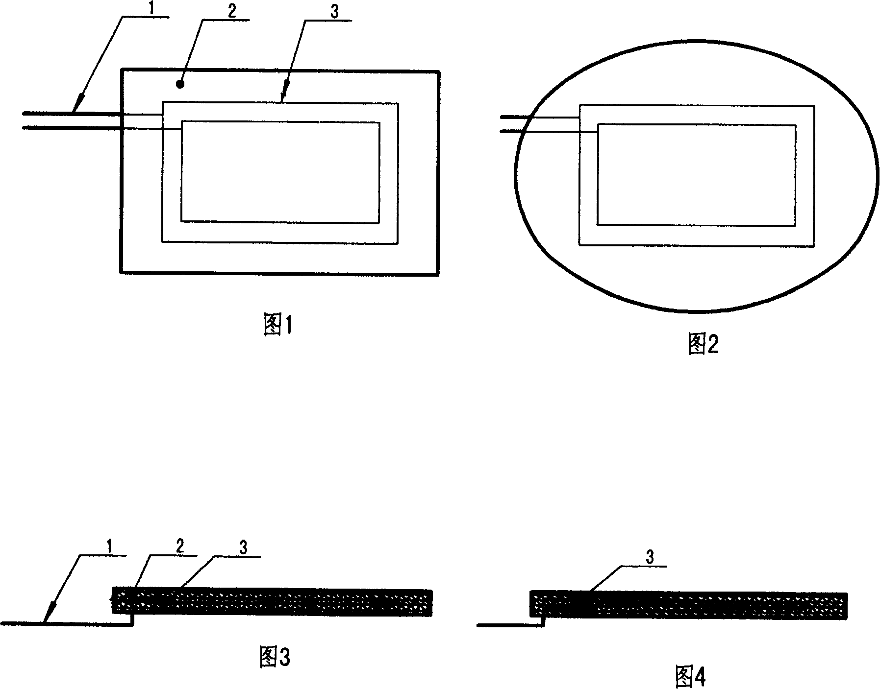
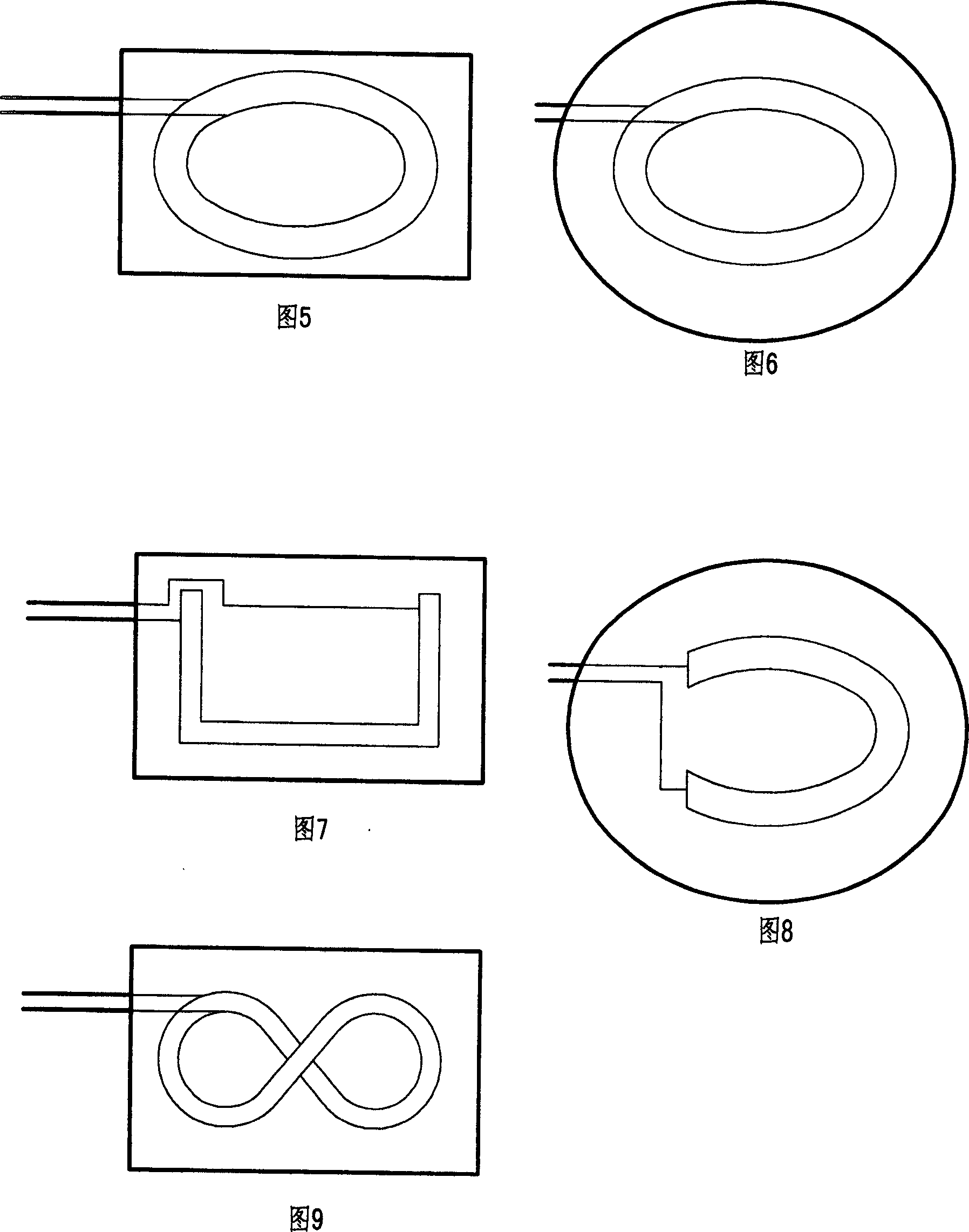
[0027] The road traffic flow detector has the same working principle as the existing flow detector. The induction signal is generated by the vibration of the conductor coil 3 when the vehicle passes by, and the induction signal leads to two signal lines forming a loop through the conductor coil. 1. Connect to a detection counter (not shown in the embodiment), and perform traffic statistics through the main control room through the detection counter. The conductor coil is a commonly used product at present, so it is not necessary to repeat it here. The innovation point of the present invention is: the conductor coil in a certain shape is fixed in the base band 2 in a certain shape, and the base band can be fixed on the roadway.

[0028] The conductor coil in a c...


PUM


Abstract

This invention relates to a road traffic flow tester charactering in fixing a conductor coil in a certain shape in a baseband in a certain shape mounted on a roadway fixedly, in which, the structure is simple and installation does not break road surfaces or the base and is very convenient, and the flow tester can be fixed on a roadway in any way and used repeatedly.

Description

technical field [0001] The invention belongs to the field of traffic facilities, in particular to a road traffic flow detector. Background technique [0002] With the rapid development of urban road traffic, the urban traffic flow is increasing. If the channeling is not good, it will inhibit the development of all aspects of the city. The implementation of urban road traffic flow detection is very important for scientifically formulating urban road construction plans and timely guiding and diverting traffic. Therefore, flow detection devices are basically installed on urban arterial roads and major traffic sections. At present, the detection device of urban traffic flow generally adopts the method of digging a certain depth under the ground of each lane to embed the flow detection coil, and then leads the signal connection from the ground and connects it to the detection counter beside the road. The disadvantages are: 1. The coil is buried in the ground at one time by slott...

Claims


Application Information

Patent Timeline
Patent Type & Authority Applications(China)
IPC IPC(8): G08G1/042
Inventor 庞文升王亮武凤池高雅新卢晓东程韫琳
Owner 天津市公安交通管理局
Learn More