Yarn feeding device

A technology of yarn feeding device and adjusting device, which is applied in transportation and packaging, thin material handling, textiles and paper making, etc. It can solve the problems of individual yarn tension, achieve good yarn control, precise yarn tension, and ensure yarn separation effect

Inactive Publication Date: 2007-08-22
IRO AB
View PDF1 Cites 5 Cited by
  • Summary
  • Abstract
  • Description
  • Claims
  • Application Information

AI Technical Summary

Problems solved by technology

However, this yarn feeding device causes problems when it is used in flat knitting machines, so-called body machines, chain looms, hosiery knit

Method used


Image

  • Yarn feeding device
  • Yarn feeding device
  • Yarn feeding device

Examples


Embodiment Construction

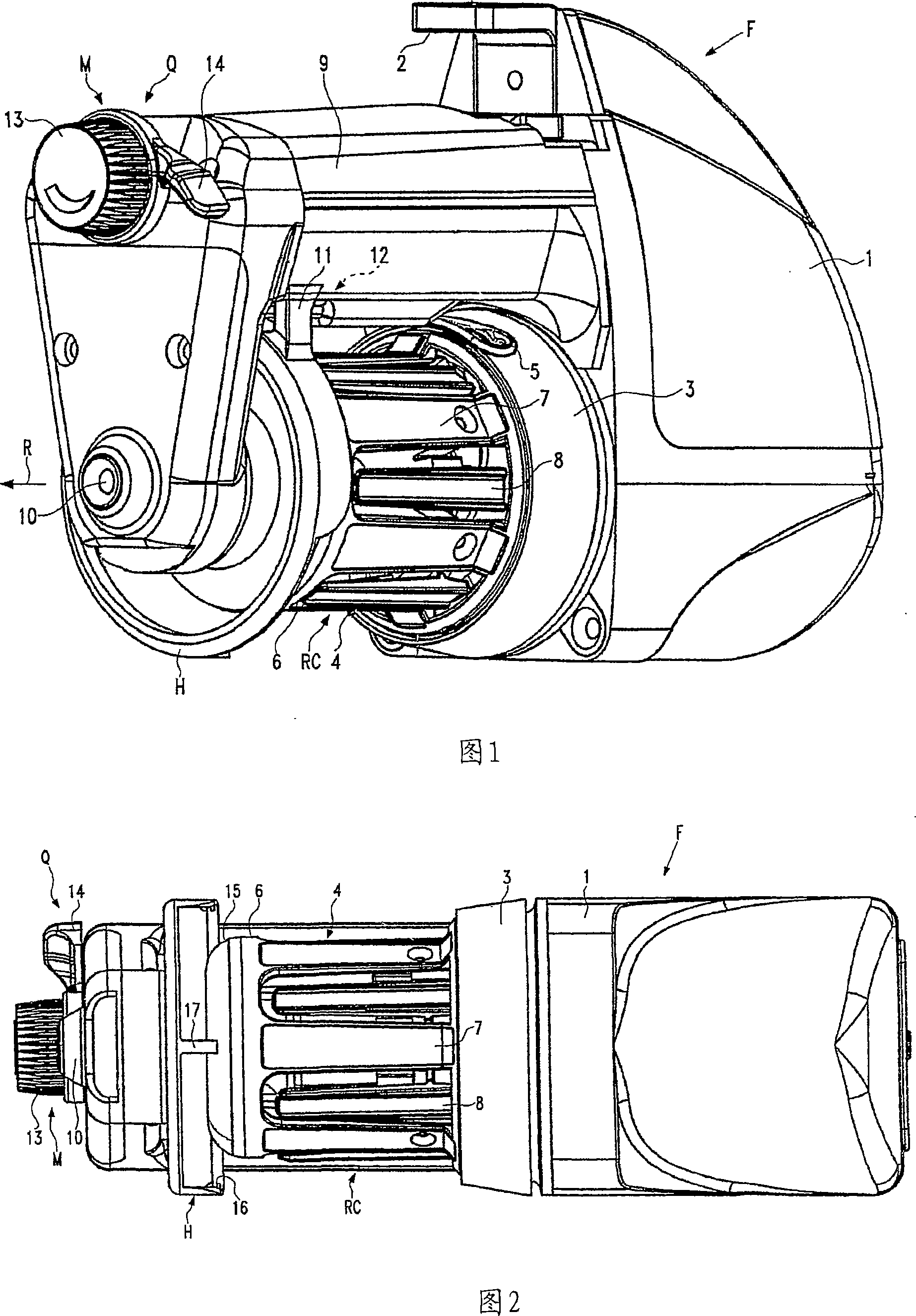
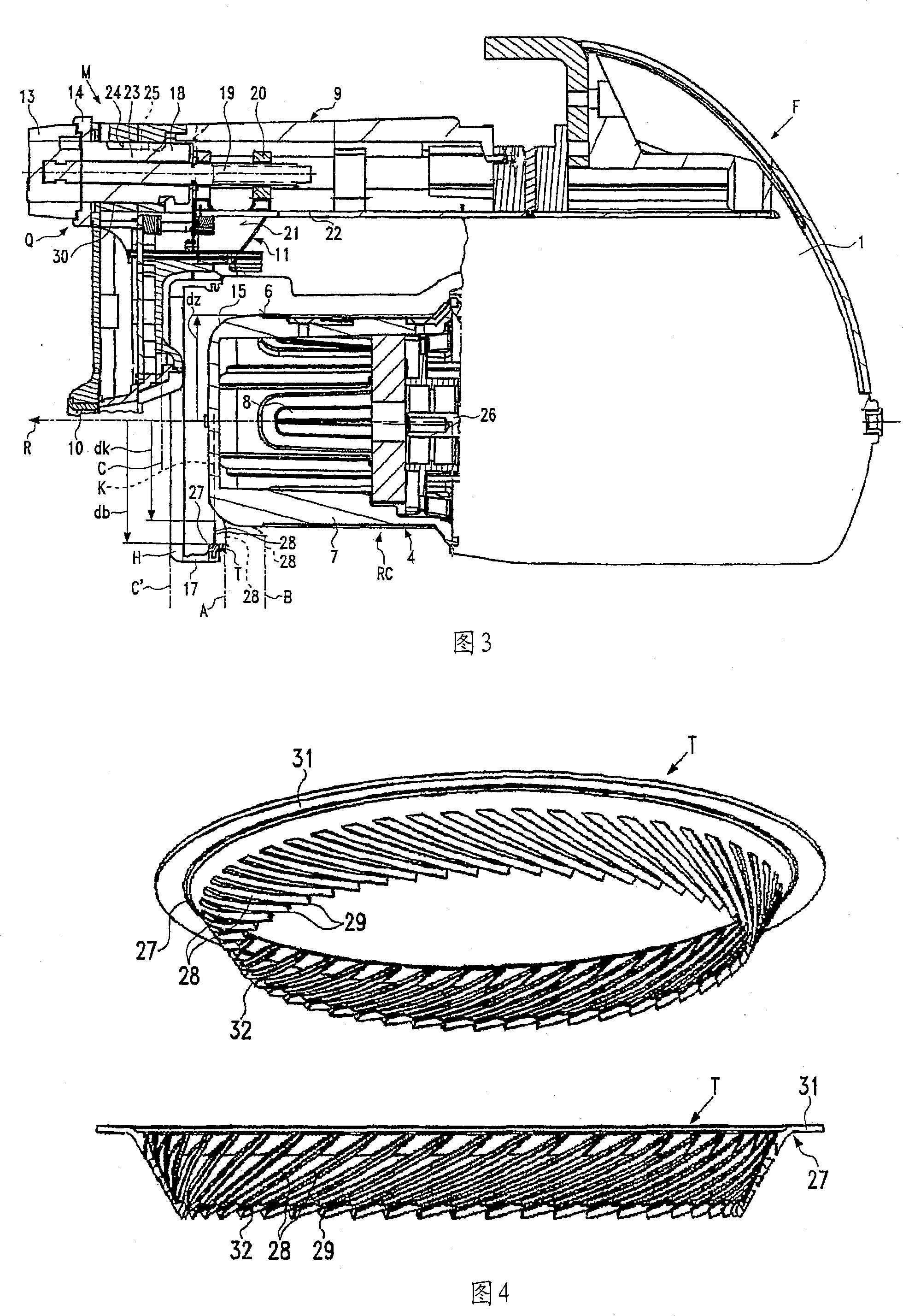
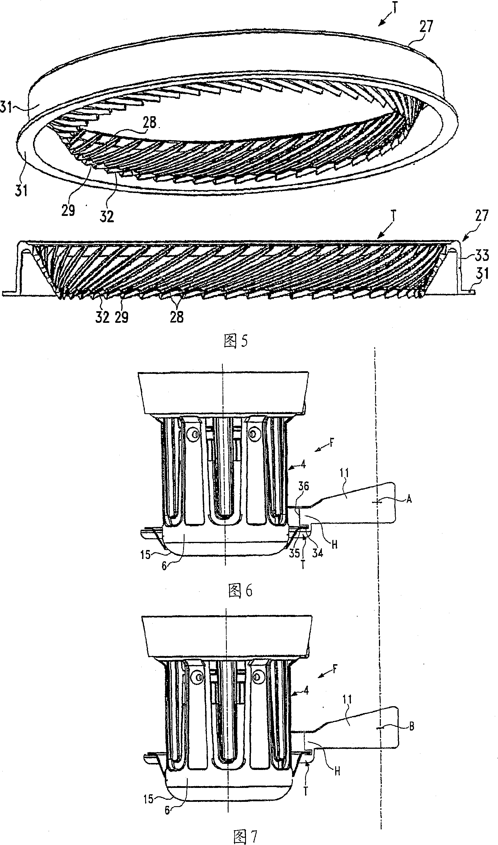
[0030]A yarn feeding device F usable for different types of knitting machines, as shown in Figures 1 to 3, comprises a housing 1 of consolidation 2, a rotatably driven winding unit 3 comprising yarn eyelets 5 and an opposite The yarn storage body 4 fixed on the winding unit 3. The yarn storage body 4 is drum-shaped and has a front cylindrical front end 6 in the unwinding direction, a front unwinding unwinding rim 15 which is circular in this embodiment, and a cylindrical Rod cage structure RC between front end 6 and winding unit 3 . Said rod cage structure RC comprises conveying rods 7 equidistantly distributed in the circumferential direction, and the conveying rods 7 are uninterrupted at least through their edges into the cylindrical front end 6 . A separating rod 8 is provided between the transport rods 7 , which can be driven due to the swinging separating movement. The separating movement of the separating lever 8 originates from an inclined rotatable bearing on the cen...


PUM


Abstract

A yarn feeding device (F) for knitting machines comprises a housing (1), a stationary storage body (4) having a cylindrical front end section (6) and a withdrawal rim (15) tapered in withdrawal direction R, a housing bracket (9) provided alongside the storage body, and a tension ring (T) which is axially adjustable in the housing bracket (9) by means of an adjustment mechanism (M) for co-action with the storage body (4) which co-action influences the yarn tension. The tension ring (T) has an outer ring body (27) and inwardly protruding fingers (28) with free finger ends (29) which follow each other in circumferential direction along a circle (K). The adjustment mechanism (M) is designed with an axial adjustment range for the tension ring (T) within which the tension ring (T) is adjustable at least between an individual yarn tension operative position (A) axially contacting the withdrawal rim (15) and a uniform yarn tension operative position (B) radially contacting the cylindrical front end section (6).

Description

technical field [0001] The invention relates to a yarn feeding device according to the preamble of claim 1 . Background technique [0002] From the technical information publication: "The storage body feeder NOVAKNIT 1000", 11.905.004 DCNA / 5 of Memminger-IRO GmbH, Dornstetten, Germany, the known yarn feeding device comprises a tension ring in the holder, the tension The ring is specially designed to cooperate with the circular unwinding rim that holds the storage body. Tension rings are available in different sizes and can be fitted into the holder, but always only work with circular unwinding rims. The adjustment device is designed such that the holder is unwound after an adjustment stroke in the direction of the winding unit and the free end of the finger of the tension ring is unwound from the cylindrical part of the storage body. Stop before the rim slips. Said known yarn feeding device is recommended for flat knitting machines, chain knitting machines and hosiery kni...

Claims


Application Information

Patent Timeline
IPC IPC(8): B65H51/22
CPCD03D47/366D04B15/484
Inventor 库尔特・阿尔内・贡纳尔・雅各布松
Owner IRO AB
Why Eureka
Try Eureka