

Electric car control apparatus
A technology for control devices and electric vehicles, which is applied to electric devices, electric vehicles, deceleration devices of AC motors, etc., can solve the problem of inability to detect partial grounding of braking resistors
- Summary
- Abstract
- Description
- Claims
- Application Information
AI Technical Summary
Problems solved by technology
Method used
Image

Examples
no. 1 Embodiment approach
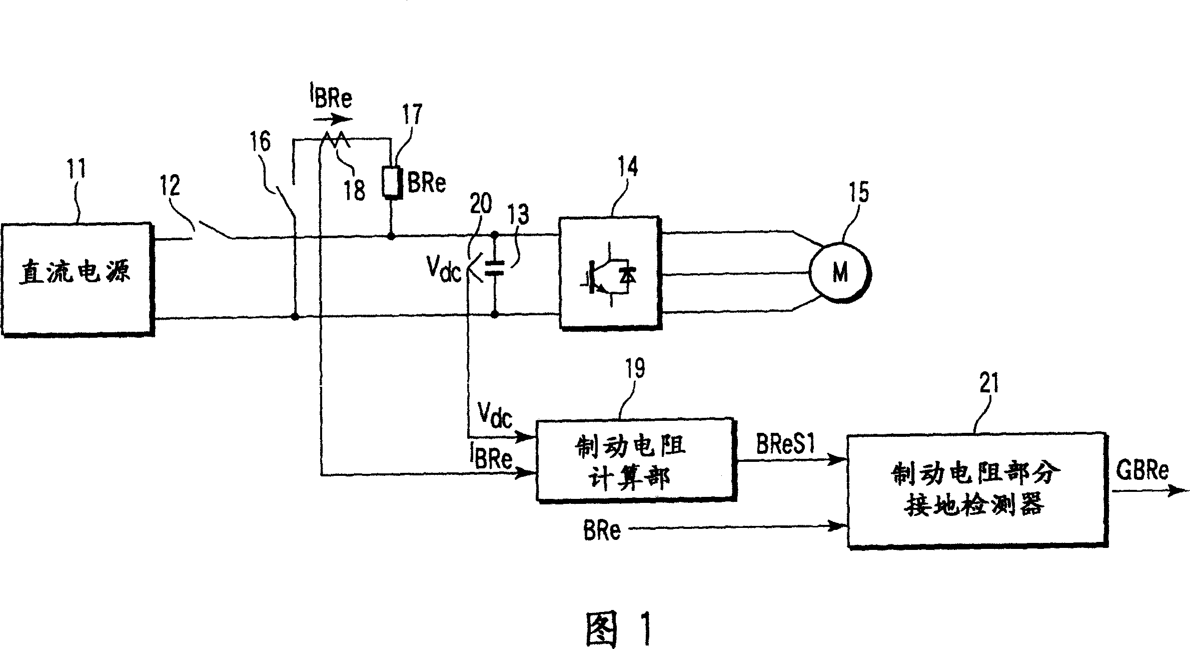
[0019] FIG. 1 is a configuration diagram of an electric train control device according to a first embodiment of the present invention. Hereinafter, the same symbol is assigned to the same part and its detailed description is omitted, and the different parts are mainly described. Repeated descriptions will also be omitted for subsequent embodiments.
[0020] The DC power supply 11 uses a rectifier to rectify, for example, electric power generated by a DC tram line (catenary) or an on-board engine generator, and outputs DC power. The DC power supply 11 is connected to a DC terminal of an inverter 14 via a first switch 12 . Filter capacitor 13 is connected between DC terminals of inverter 14 on the side closer to inverter 14 than first switch 12 . The inverter 14 is connected to an AC motor 15 as a load on the output side. Usually, an induction motor is used as the AC motor 15 . In addition, variable voltage variable frequency (VVVF) operation control is performed on the inve...
no. 2 Embodiment approach
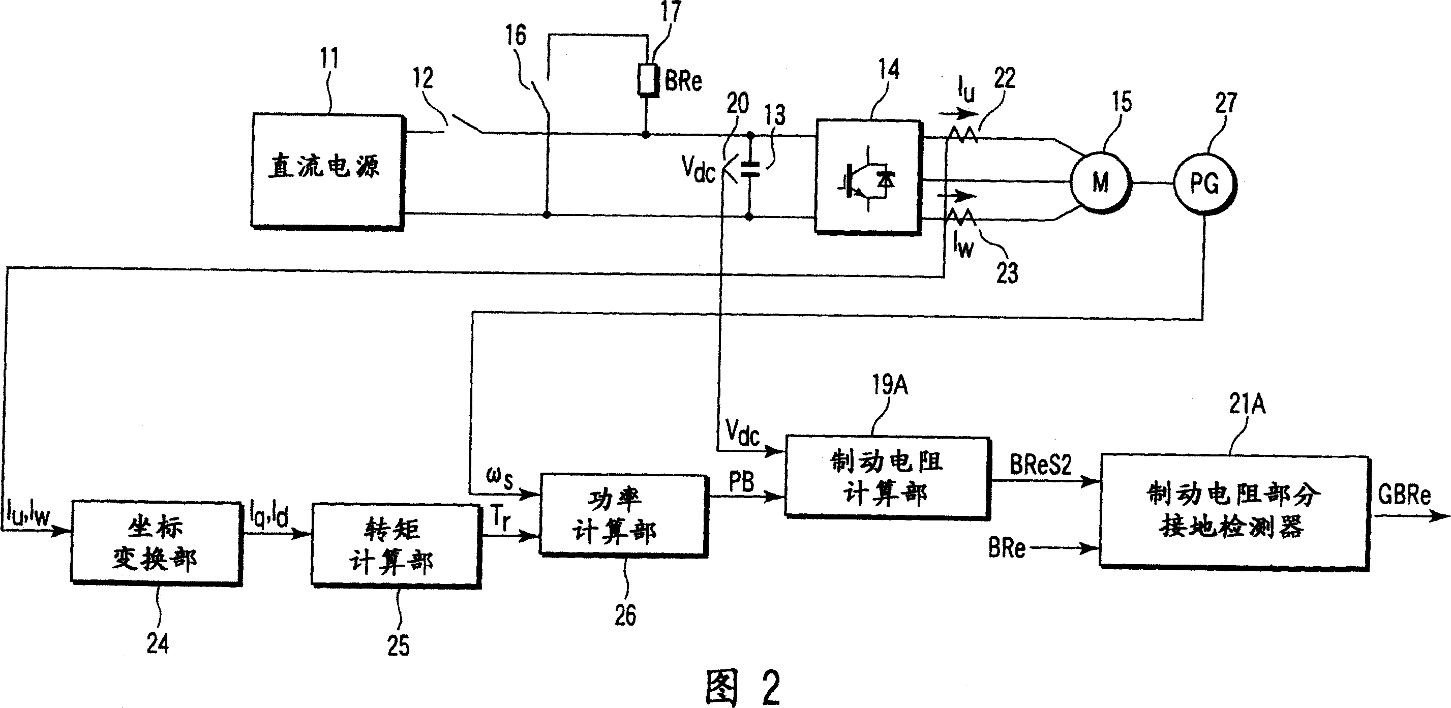
[0029] Fig. 2 is a block diagram of an electric train control device according to a second embodiment of the present invention. In the second embodiment, in the first embodiment shown in FIG. 1 , instead of the braking resistance calculation unit 19 and the braking resistance partial grounding detector 21 , a braking resistance calculation unit 19A and a braking resistance partial grounding detector 21A are provided. , a coordinate conversion unit 24 , a torque calculation unit 25 and a power calculation unit 26 . In addition, instead of the current detector 18, a current detector 22, a current detector 23, and a speed sensor 27 are provided.
[0030] Brake resistor calculation unit 19A calculates resistance value BReS2 of brake resistor 17 based on brake power PB and voltage value Vdc of brake resistor 17 .
[0031] The current detector 22 detects the u-phase current value Iu of the AC motor 15 . The current detector 23 detects a w-phase current value Iw of the AC motor 15 ...
no. 3 Embodiment approach
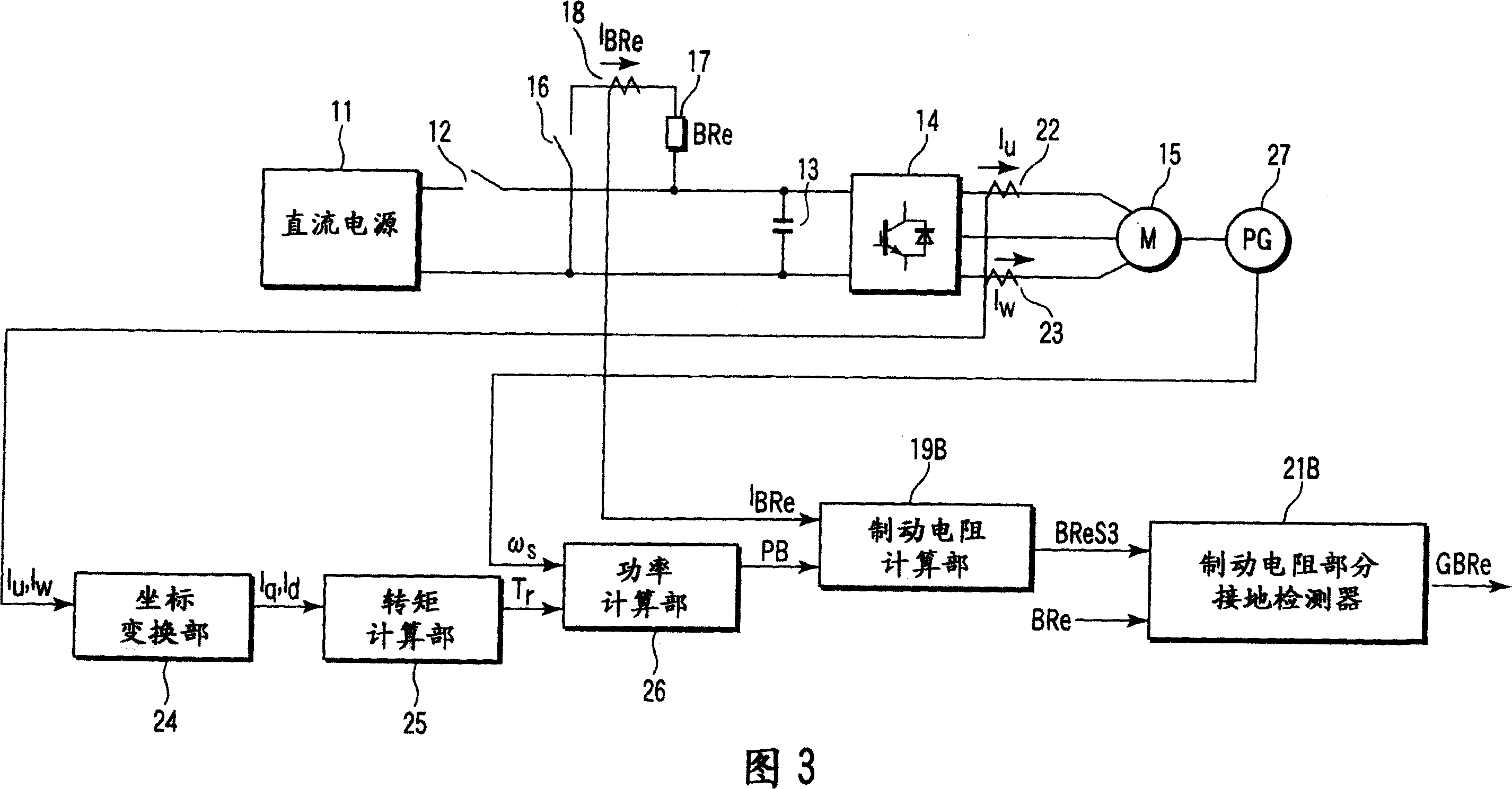
[0044] Fig. 3 is a block diagram of an electric train control device according to a third embodiment of the present invention. In the third embodiment, in the second embodiment shown in FIG. 2 , instead of the braking resistance calculation unit 19A and the braking resistance partial grounding detector 21A, a braking resistance calculation unit 19B and a braking resistance partial grounding detector 21B are provided. . In addition, instead of the voltage detector 20, a current detector 18 is provided.
[0045] The braking resistance calculation unit 19B calculates the resistance value BReS3 of the braking resistor 17 based on the braking power PB and the current value IBRe.
[0046] The current value IBRe detected by the current detector 18 is input to the braking resistance calculation unit 19B. The braking power PB calculated by the power calculating unit 26 is input to the braking resistor calculating unit 19B. The braking resistance calculation unit 19B receives the inp...
PUM
 Abstract
Description
Claims
Application Information