Multifunction pouring spout with handle

A handle and launder technology, applied in container handles, painting tools, decorative arts, etc., can solve the problems of no handle, difficulty in removing, and failure to do so.

Inactive Publication Date: 2007-08-29
ALLWAY TOOLS
View PDF1 Cites 6 Cited by
  • Summary
  • Abstract
  • Description
  • Claims
  • Application Information

AI Technical Summary

Problems solved by technology

The paint in this seal groove causes the following problems: First, if the metal paint can lid is placed on the can roof and into the groove before the paint dries, the paint acts as an adhesive, sealing the lid to the can and making the Subsequent removal becomes difficult
While painters are aware of this problem, they choose to wipe their brushes against the inside edge because the alternate method (that is, applying excess paint to a given area) can ruin the job at hand, thereby completely ruining their results
[0007] Also, while it is good practice to put the paint lid back on the can to keep the paint fresh during the night or during lunch breaks, many people fail to do this and introduce paint to the side of the can lid and the seal recess. in the slot
[0008] Another problem is that when the paint can is full of paint, due to the weight of the paint can, it is physically necessary to hold the filled paint can by the wire handle provided on the standard one gallon paint can
Furthermore, when the can is held by the handle, since the handle is placed just above the opening from which the paint can is hung, it prevents the paint brush from dipping into the can, forcing the user to position the brush in such a way that the brush does not come into contact with the handle of the paint can and control the direction of the brush
Furthermore, in smaller one-quart paint containers, which typically do not have handles, it is especially daunting to continuously hold the can by hand by the outside of the can without suffering muscle cramps and fatigue

Method used


Image

  • Multifunction pouring spout with handle
  • Multifunction pouring spout with handle
  • Multifunction pouring spout with handle

Examples


Embodiment Construction

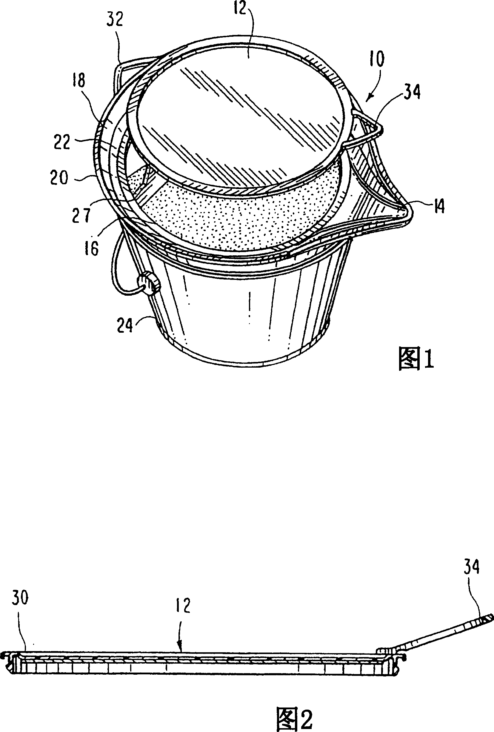
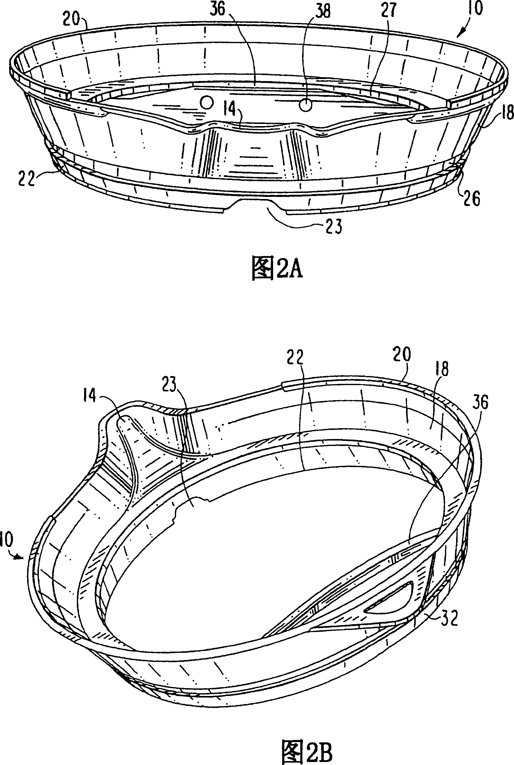
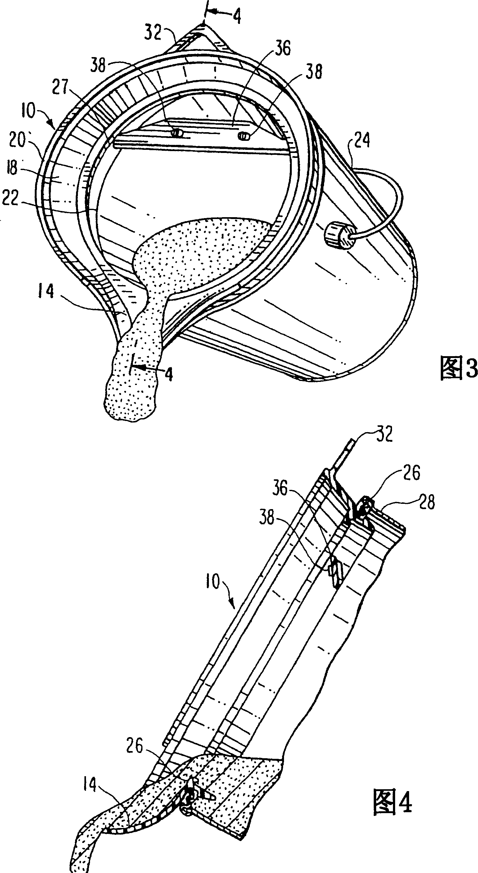
[0043]Referring to the drawings, Figure 1 depicts a preferred embodiment of the pouring spout (10) of the present invention having a removable plug or lid (12). Each launder (10) also has a mouth (14), a central circular opening (16) and side surfaces forming a wall (18) with an upper edge or rim (20) and a lower edge or rim (twenty two). Preferably, the side surfaces are created at an angle greater than ninety degrees from the horizontal, such that the walls (18) are formed sloping outwards and upwards from the center and lower edge (22) of the launder (10). Of course, the side surfaces can also extend at angles of 90 degrees and less than 90 degrees from the horizontal surface of the container. In addition to forming the walls (18) of the launder (10), the side surfaces also form the mouth (14). The mouth (14) extends outwardly beyond the perimeter of the wall (18), which forms a channel through which fluid exits its container. As the channel protrudes away from the cente...


PUM


Abstract

An inventive pouring spout that is selectively attachable to a container and fitted to the opening of the container with which it is used. In a preferred embodiment, the pouring spout is fitted to the dimensions of a one-quart container and includes a wall, a sealing member, a mouth and a handle, the mouth and handle extending from the wall. The handle includes a plurality of upwardly extending projections adapted to securely engage the bottom rim of the container. Furthermore, thermoplastic material is applied at the handle area forming a handle cover that is comfortable and easy to grip. Thermoplastic material is also preferably utilized in the construction of the sealing member for forming a seal between the spout and opening of the container.

Description

[0001] related application [0002] This application is a continuation-in-part of Application Serial No. 10 / 830,275, filed April 22, 2004, which is hereby incorporated by reference. technical field [0003] The present invention relates to a multifunctional lid for containers such as paint cans. More specifically, the present invention relates to a detachable pouring spout with a removable cover that prevents dripping and splashing of paint along the sides and around the opening of the paint can. Furthermore, as another embodiment, the present invention relates to a detachable pouring spout having a handle, which allows a user to easily hold a paint can. Background technique [0004] Common paint cans have a number of disadvantages for both professional and amateur painters. In particular, the construction of common gallon-sized paint cans may make it nearly impossible to pour paint from the can into a paint pan or other container without the paint being poured along the s...

Claims


Application Information

Patent Timeline
Patent Type & Authority Applications(China)
IPC IPC(8): B65D23/06B65D47/40B65D53/00B65D23/10B65D23/12B65D21/02B44D3/12
Inventor 唐纳德·格林杰程元方
Owner ALLWAY TOOLS
Why Eureka
Try Eureka