External transverse prestressed steel reinforced concrete beam

A reinforced concrete beam, transverse prestressing technology, applied in the direction of joists, girders, truss beams, etc., to achieve the effect of improving shear resistance, shear bearing capacity and shear resistance, and shear bearing capacity

Inactive Publication Date: 2007-08-29
SOUTH CHINA UNIV OF TECH
View PDF0 Cites 20 Cited by
  • Summary
  • Abstract
  • Description
  • Claims
  • Application Information

AI Technical Summary

Problems solved by technology

[0004] The purpose of the present invention is exactly to overcome the deficiencies in the prior art, to provide external transverse prestressed reinforced concrete beams, by applying transverse prestressed externally to reinforced concrete beams, improve the shear bearing capacity and shear cracking resistance of reinforced concrete beams, Solve the problem of reinforcement of reinforced concrete transfer beam

Method used


Image

  • External transverse prestressed steel reinforced concrete beam
  • External transverse prestressed steel reinforced concrete beam
  • External transverse prestressed steel reinforced concrete beam

Examples


Embodiment 1

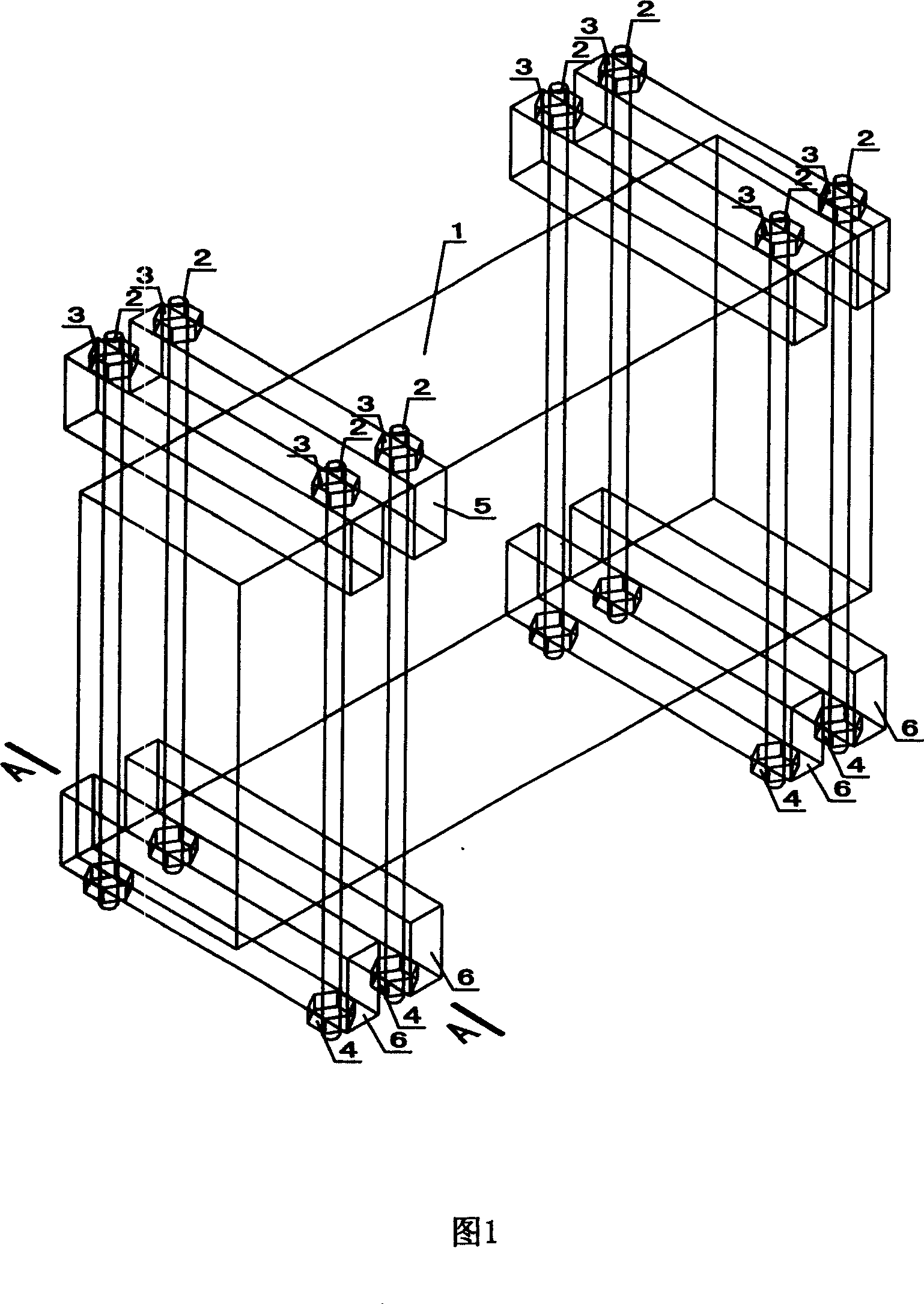
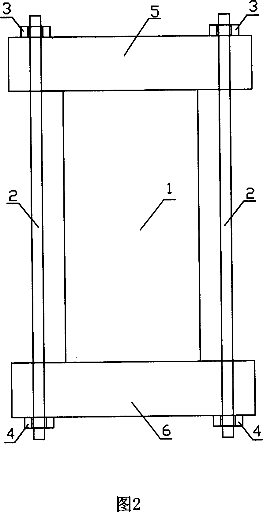
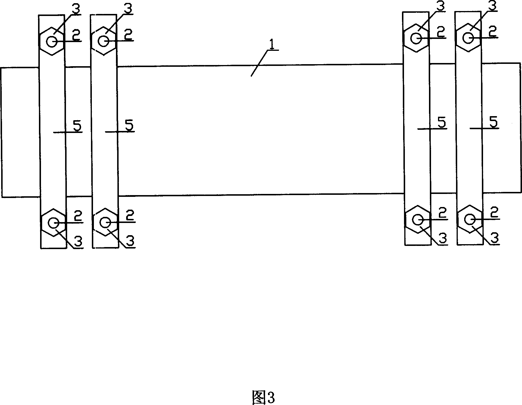
[0022] As shown in Figures 1, 2 and 3, an external transverse prestressed reinforced concrete beam includes a reinforced concrete beam 1, a tie rod 2, an upper anchor 3, a lower anchor 4, an upper pressure piece 5 and a lower pressure piece 6. Four upper pressing pieces 5 and lower pressing pieces 6 are respectively arranged on the upper surface and the lower surface of the reinforced concrete beam 1, the length of the upper pressing piece 5 and the lower pressing piece 6 are greater than the width of the reinforced concrete beam 1, and both ends of the upper pressing piece 5 and the lower pressing piece 6 are arranged along the The concrete beam 1 protrudes in the width direction, and the upper pressing part 5 and the lower pressing part 6 are provided with a row of holes on both sides of the width direction of the reinforced concrete beam 1, and the tie rod 2 passes through the upper pressing part on the two outer sides of the reinforced concrete beam 1 width. A piece 5 and a...

Embodiment 2

[0028] Considering that the bearing capacity of the original reinforced concrete transfer beam is quite different from the actual needs, by increasing the number of tie rods 2, the method of increasing the number of rows and columns of tie rods is adopted. In this embodiment, six upper pressing pieces 5 and lower pressing pieces 6 are respectively arranged symmetrically on the upper surface and the lower surface of the reinforced concrete beam 1, and each upper pressing piece 5 and lower pressing piece 6 are arranged in the width direction of the reinforced concrete beam 1. A row of tunnels are arranged on both sides of the exterior. The tie rod 2 passes through the upper pressing part 5 and the lower pressing part 6 on the two outer sides of the width of the reinforced concrete beam 1. After the tie rod 2 is tightened, it passes through the upper anchorage 3 and the The lower anchorage 4 is fixed between the upper pressing piece 5 and the lower pressing piece 6, and the streng...

Embodiment 3

[0030] If the height of the original reinforced concrete transfer beam is limited, but the tie rod 2 needs to be longer to avoid excessive prestress loss, the tie rod 2 should be arranged obliquely. As shown in Figure 5, a row of tunnels are arranged on the outer sides of the reinforced concrete beam 1 in the width direction of the upper pressure piece 5 and the lower pressure piece 6, and the holes on the upper pressure piece 5 and the lower pressure piece 6 are not in the same vertical direction. On the line, but staggered by a certain distance, facing diagonally. In this way, the tie rod 2 and the bottom surface of the reinforced concrete beam 1 pass through the upper pressing part 5 and the lower pressing part 6 at an angle. Others are the same as embodiment 1.


PUM


Abstract

The invention discloses an external horizontal prestressed reinforced concrete beam whose upper and lower surfaces are oppositely equipped with multiple upper and lower press pieces respectively, the two sides of each of the upper and lower press piece are both equipped oppositely with at least a row of holes, where a pull rod runs through the upper and lower press pieces, and is strained and fixed between the upper and lower press pieces through upper and lower anchors at its two ends. As compared with the common reinforced concrete beam, the invention adds prestressed bars on the two sides of the reinforced concrete beam, increasing hoop reinforcement area and making the concrete in a pressed state by prestressing the pull rods, thus improving concrete shearing strength. And the invention reduces the size of the reinforced concrete beam, saving material and increasing construction use space, applied to reinforce the existing and new built reinforced concrete beams and.

Description

technical field [0001] The invention relates to applying transverse prestress to a reinforced concrete beam, and the pull rod is arranged outside the reinforced concrete beam, so as to improve the shear bearing capacity and shear cracking resistance of the reinforced concrete beam. Background technique [0002] Setting reinforced concrete beams as transfer members in high-rise building structures is a common technical means in the design of high-rise building structures. The cross-sectional size of reinforced concrete transfer beams is usually controlled by the shear capacity. When the use function of the building structure is changed, the design is changed, or there are construction quality problems, it is necessary to perform shear reinforcement on the reinforced concrete transfer beam. [0003] The method of reinforcement generally adopts enlarging its section, but enlarging the section, on the one hand, is not conducive to the earthquake resistance of the structure, on t...

Claims


Application Information

Patent Timeline
Patent Type & Authority Applications(China)
IPC IPC(8): E04G23/02E04C3/26
Inventor 吴波王帆
Owner SOUTH CHINA UNIV OF TECH
Why Eureka
Try Eureka