Optical scanning module

An optical scanning, to-be-scanned technology, applied in image communication, electrical components, etc., can solve the problems of occupying the space of the scanning module and unfavorable thinning of the scanner.

Inactive Publication Date: 2007-08-29
PRIMAX ELECTRONICS LTD
View PDF1 Cites 5 Cited by
  • Summary
  • Abstract
  • Description
  • Claims
  • Application Information

AI Technical Summary

Problems solved by technology

However, the heat dissipation device 236 mentioned in this patent case is mainly completed by using heat pipes filled with cooling liquid and heat sinks. The arrangement of these heat dissipation elements will occupy the space of the scanning module, which is not conducive to the purpose of thinning the scanner.

Method used


Image

  • Optical scanning module
  • Optical scanning module
  • Optical scanning module

Examples


Embodiment Construction

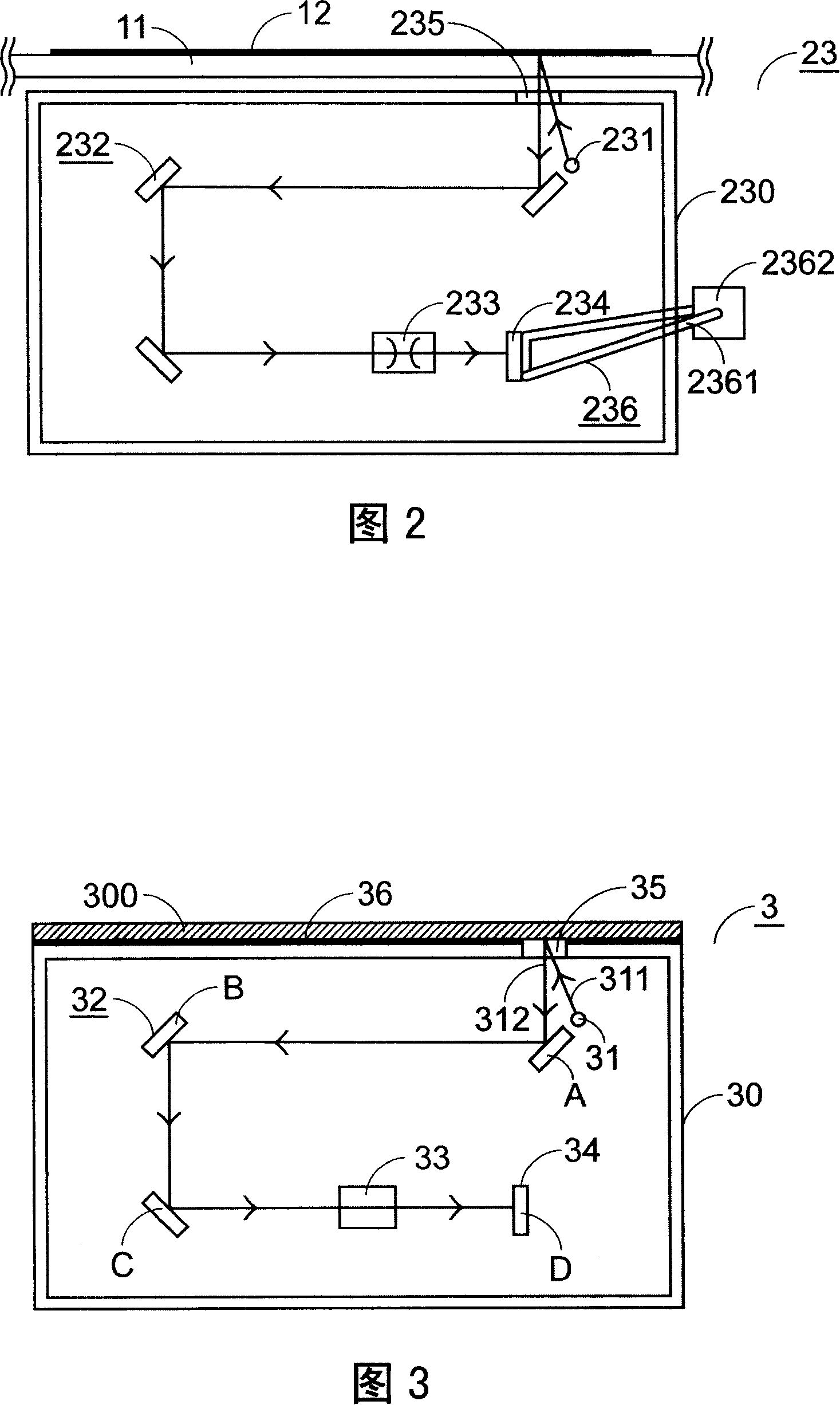
[0045] Please refer to FIG. 3 , which is a schematic diagram of the internal components of a preferred embodiment of the optical scanning module 3 developed by the present invention to improve the shortcomings of known devices. The optical scanning module 3 described in the present invention is used to scan a Document 300 is image scanned in an optical scanner (not shown in this figure). We can clearly see from the figure that the optical scanning module 3 includes a casing 30, which is provided with a light source 31, a reflective lens group 32, a lens 33 and a light sensing element 34. 30 is also provided with a window 35 . Reference numeral 312 in FIG. 3 represents the reflected light reflected by the document to be scanned. The working principle among the components included in the optical scanning module 3 is the same as that of the known technology, and will not be repeated here.

[0046] Generally, the optical scanning modules that use charge-coupled devices (CCDs) as...


PUM


Abstract

The disclosed optical scanning module includes following parts: a shell body; a light source setup inside the shell body can send out light beam to irradiate file to be scanned, and the light source includes an electrode covered by insulated heat conducting rubber; a first cooling fin setup on one surface of the shell body is contacted to the insulated heat conducting rubber. The optical scanning module not only can exhale heat effectively, but also does not increase volume of optical scanning module.

Description

technical field [0001] The invention relates to an optical scanning module, in particular to an optical scanning module used in an optical scanner and capable of scanning images of documents to be scanned. Background technique [0002] Flatbed scanners have become an electronic product used by most users to scan and convert some document data into image files. This kind of scanner can make it easy and convenient for users to input document data into the computer for storage or further processing. Image processing in the computer. Please refer to FIG. 1(a), which is a schematic diagram of the appearance of a flatbed scanner. From the figure, we can clearly see that the flatbed scanner 1 includes a transparent platform 11, which can be used to place a The document 12 to be scanned, the most important element that the platform scanner 1 comprises is an optical scanning module 13, and the optical scanning module 13 images the document 12 to be scanned placed on the transparent ...

Claims


Application Information

Patent Timeline
Patent Type & Authority Applications(China)
IPC IPC(8): H04N1/024H04N1/04
Inventor 陈锡裕陈冠扬
Owner PRIMAX ELECTRONICS LTD
Why Eureka
Try Eureka