
High power barreled

A high-power, chip technology, applied in electrical components, electric solid-state devices, circuits, etc., can solve the problems of high chip junction temperature, discoloration of light-transmitting medium, accelerated light decay, etc., and achieve low chip junction temperature, high luminous efficiency, Good general effect

Inactive Publication Date: 2019-12-10
郑州希硕信息科技有限公司
View PDF0 Cites 0 Cited by
  • Summary
  • Abstract
  • Description
  • Claims
  • Application Information

AI Technical Summary

Problems solved by technology

[0003] The light emitting side of the light-emitting diode chip in the prior art has a heat-insulating light-transmitting medium and a lens, etc., and the heat generated by the chip can only be conducted from the back of the chip through the metal base, which affects the heat dissipation of the light-emitting diode chip and is easy to use. If the chip junction temperature is too high, the p-n junction of the light emitting diode chip and the place between it and the heat-insulating light-transmitting medium will become the highest temperature place in the light-emitting diode, and the light-emitting material of the white light-emitting diode in the prior art is just here, high temperature It will cause the luminous efficiency of the luminescent material to decrease, the light decay to accelerate, and the life of the light-emitting diode to be shortened; at the same time, the high temperature will also change the color of the light-transmitting medium, further shortening the life of the light-emitting diode; obstacle
[0004] In addition, high-power light-emitting diodes require large-area chips and large-volume lenses, which increase the cost and weight of light-emitting diodes

Method used


Image

  • High power barreled
  • High power barreled
  • High power barreled

Examples


Embodiment Construction

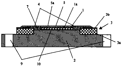
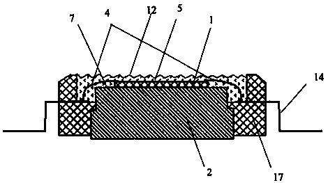
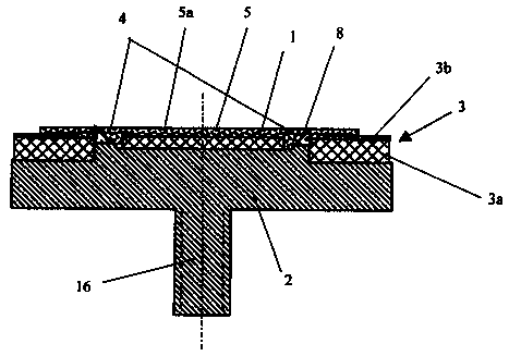
[0023] The indications in the attached drawings are:

[0024] 1-LED chip 2-Metal base 3-Electrical connection device

[0025] 3a-insulating layer 3b-conducting layer 4-lead

[0026] 5 - Light-transmitting protective layer or layer of luminescent material 5a - Luminescent material or light scattering material

[0027] 6-luminescent material layer 7-light reflection layer 8-light reflection bowl

[0028] 9-Screw hole 10-High thermal conductivity material 11-Flip chip

[0029] 12-Uneven surface 13-Light-emitting material layer 14-Metal lead wire

[0030] 15-Circuit board and metal lead wire 16-Screw 17-Insulation frame

[0031] 18-Conductive material 19-Fixing glue

[0032] The present invention will be described in detail below in conjunction with the accompanying drawings: figure 1 Shown is a schematic structural diagram of an embodiment of the high-power light emitting diode of the present invention. It includes at least one light-emitting diode chip 1, at least one met...


PUM


Abstract

The invention provides a high power bareLED which comprises at least one light emitting diode chip, at least one metal base and an electrical connection device. The light emitting diode chip is mounted on the metal base in an upward or inverted way. The electrodes of the light emitting diode chip are connected with the electrical connection device via a lead wire or an electrical connection material. The light emergent surface of the light emitting diode chip is exposed to air directly or through a light transmitting protective layer or a light emitting material layer. The heat generated by the chip can be conducted from the back of the chip through the metal base and through the light emergent surface of the chip so that the temperature rise of the chip junction and the light emitting layer is low, and the light emitting diode is enabled to have the advantages of high light emitting efficiency, high power, long service life, simple process, low cost, good universality and the like.

Description

technical field [0001] The invention relates to a high-power light-emitting diode, which is used for lighting, traffic lights, solar lights, decorative lights, displays and the like. Background technique [0002] At present, about 80% of the input electrical energy of the prior art light-emitting diode will be converted into heat energy, and its heat mainly comes from the p-n junction of the light-emitting diode chip. If the heat generated by the chip cannot be effectively conducted and dissipated effectively If it falls off, the junction temperature of the chip is easy to be too high, resulting in a serious drop in the luminous efficiency, and even burning the light-emitting diode. This is particularly serious for high-power light-emitting diodes used for lighting. This is currently a major obstacle to the use of light-emitting diodes for lighting. [0003] The light-emitting side of the LED chip in the prior art has a heat-insulating light-transmitting medium and a lens,...

Claims


Application Information

Patent Timeline
Patent Type & Authority Applications(China)
IPC IPC(8): H01L33/44H01L33/64H01L25/075
CPCH01L25/0753H01L33/44H01L33/64
Inventor 普新勇赵素珍
Owner 郑州希硕信息科技有限公司
Learn More