
A drying device for solid materials with an internal turning mechanism

A technology of solid material and drying device, which is applied in the direction of drying solid material, drying gas arrangement, heating device, etc., can solve the problems of not being effectively used, reducing the use effect of the device, and troublesome installation and positioning, so as to improve the speed and convenience Sexuality, convenient and quick to use, and the effect of improving the drying effect

Active Publication Date: 2021-10-01
江苏瀚高科技有限公司
View PDF1 Cites 0 Cited by
  • Summary
  • Abstract
  • Description
  • Claims
  • Application Information

AI Technical Summary

Problems solved by technology

[0004] The purpose of the present invention is: in order to solve the problem that the traditional drying device is not equipped with a structure that can quickly locate the material, and it is troublesome to install and position it, and at the same time, there is no turning mechanism in the device. It is impossible to change the drying position of the drying material. At the same time, there is no structure designed to quickly improve the drying efficiency, which reduces the use effect of the device. At the same time, the device is not equipped with a waste heat recovery device. After the material is dried, the waste heat in the device is only Energy can be lost naturally, can not be used effectively, and heat is wasted, so a drying device for solid materials with an internal turning mechanism is proposed.

Method used


Image

  • A drying device for solid materials with an internal turning mechanism
  • A drying device for solid materials with an internal turning mechanism
  • A drying device for solid materials with an internal turning mechanism

Examples


Embodiment Construction

[0042] The following will clearly and completely describe the technical solutions in the embodiments of the present invention with reference to the accompanying drawings in the embodiments of the present invention. Obviously, the described embodiments are only some, not all, embodiments of the present invention. Based on the embodiments of the present invention, all other embodiments obtained by persons of ordinary skill in the art without creative efforts fall within the protection scope of the present invention.

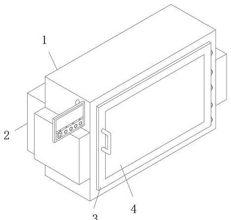
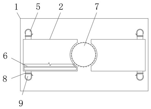
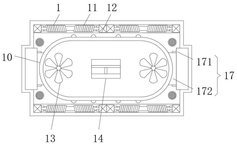
[0043] see Figure 1-10 , the present invention provides a technical solution: a drying device for solid materials with an internal turning mechanism, including a casing 1, a heat recovery water tank 2 is fixedly installed on the rear outer wall of the casing 1, and the heat recovery water tank 2 is fixedly installed with an inner partition 6, and a heat radiation shell 12 is fixedly installed on the top and bottom inner walls of the casing 1, and an electric heati...


PUM


Abstract

The invention discloses a drying device for solid materials with an internal turning mechanism, which belongs to the technical field of drying solid materials, and comprises a casing, and a heat recovery water tank is fixedly installed on the outer wall of the rear side of the casing; There is an air guide assembly, when the driving motor is turned on, it drives the transmission chain plate of the air guide assembly to drive, and at the same time drives the transmission of the air guide inner cover, and at the same time drives the turbulence fan with the driven gear to rotate, so as to realize the rotation of the solid material clamping and flipping assembly At the same time, the effect of the transmission of the air guide assembly and the rotation of the spoiler fan, the rotating spoiler fan can effectively quickly disturb the hot air flow inside the air guide assembly, and at the same time, the transmission of the air guide assembly can play the role of an air collector, and the wind guide The turbulent flow of hot air inside the component is concentrated at the position of the solid material clamping and flipping component in the middle, which can effectively avoid heat loss and greatly improve the drying efficiency and effect of the liquid of the solid material mounted on the solid material clamping and flipping component.

Description

technical field [0001] The invention belongs to the technical field of solid material drying, in particular to a drying device for solid material with an internal turning mechanism. Background technique [0002] Material is a noun. With the development of science and technology, various materials have been discovered. Different materials have different functional effects. Different materials are also used in different fields and different structures to play different roles. Function, in which materials are divided according to the form, mainly divided into solid materials and liquid materials, solid materials and liquid materials are also used in different scenarios, some solid materials need to be kept dry when they are applied, and a dry material is required at this time device. [0003] Chinese patent (CN209926759U) discloses a drying device for electronic liquid processing, including a drying box, including a horizontal partition in the drying box, which divides the dry...

Claims


Application Information

Patent Timeline
Patent Type & Authority Patents(China)
IPC IPC(8): F26B11/18F26B21/00F26B23/06F26B25/00F26B25/02F26B25/18B08B1/04
CPCB08B1/04F26B11/18F26B21/001F26B21/004F26B23/06F26B25/005F26B25/02F26B25/18Y02P70/10
Inventor 王红军
Owner 江苏瀚高科技有限公司
Learn More