
Pressure mounting device and pressure mounting method

An installation device and pressure technology, applied in electrical components, electrical components, etc., can solve the problems of low curing speed of thermally conductive adhesive, low reliability, limited space between chips, etc., to improve practicability and versatility, and ensure flexibility. and versatility, the effect of saving installation space

Inactive Publication Date: 2007-08-29
NEW H3C TECH CO LTD
View PDF0 Cites 9 Cited by
  • Summary
  • Abstract
  • Description
  • Claims
  • Application Information

AI Technical Summary

Problems solved by technology

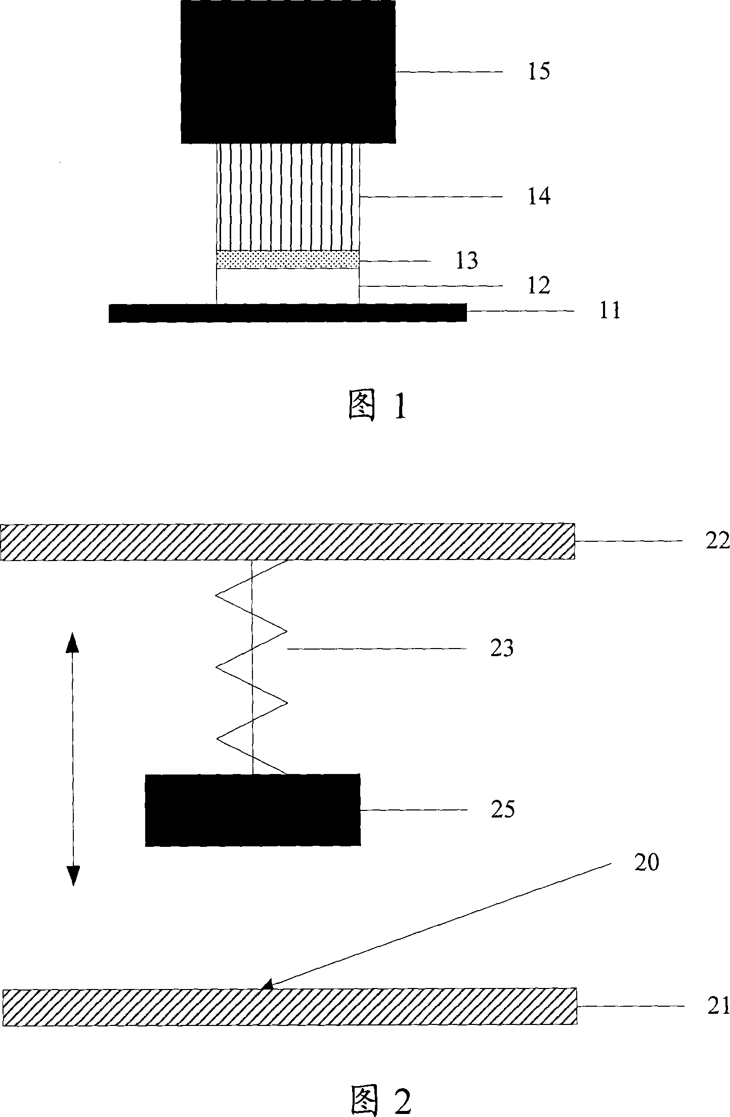
[0007]1. Relying entirely on manual work, the installation efficiency is low; the installation effect is affected by factors such as the skill level of the assembler, work mood, etc. stability and may cause physical damage to the chip or heatsink
[0008]2. Each installation requires pressing blocks. For large quantities of parallel installations, it is necessary to provide more space for placing pressing blocks, supporting molds and these installation tools. Too many consumables are used and it takes up a lot of space; the pressure depends on the weight of the briquetting block, and the volume of the briquetting block with a larger weight is usually larger. During installation, due to the limited space between chips, it may not be possible to place a large weight compact
[0009]3. The curing speed of thermal conductive adhesive is low, so the exposure time is very long, and it is easy to be polluted by the environment, thereby reducing the bonding strength and reliability of the colloid; the curing time of thermal conductive adhesive Long, resulting in a long installation period, making the installation efficiency very low
[0010] It can be seen that the existing heat sink installation technology has low efficiency, low reliability and high cost

Method used


Image

  • Pressure mounting device and pressure mounting method
  • Pressure mounting device and pressure mounting method
  • Pressure mounting device and pressure mounting method

Examples


Embodiment Construction

[0042] In order to make the object, technical solution and advantages of the present invention clearer, the present invention will be further described in detail below with reference to the accompanying drawings and examples.

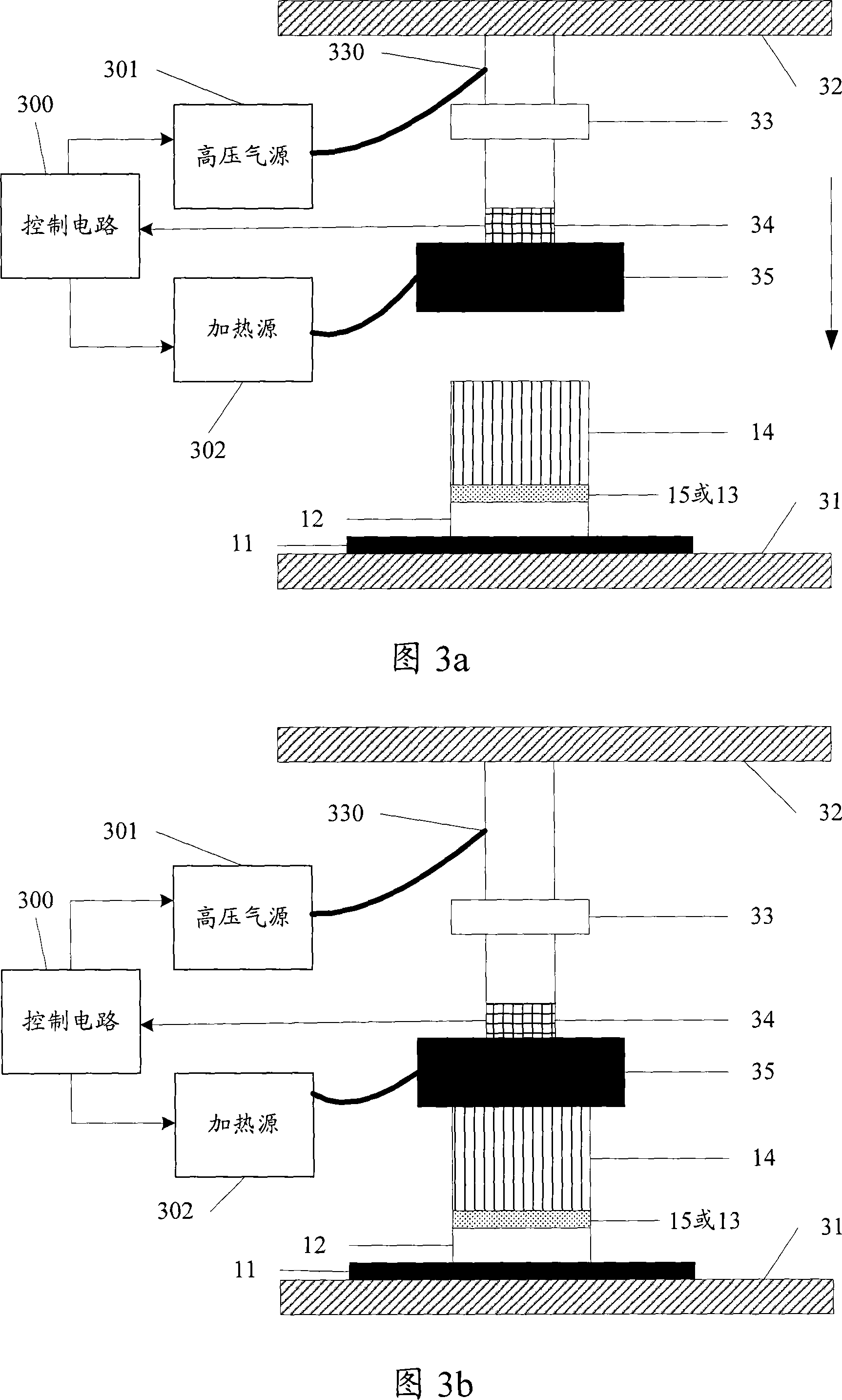
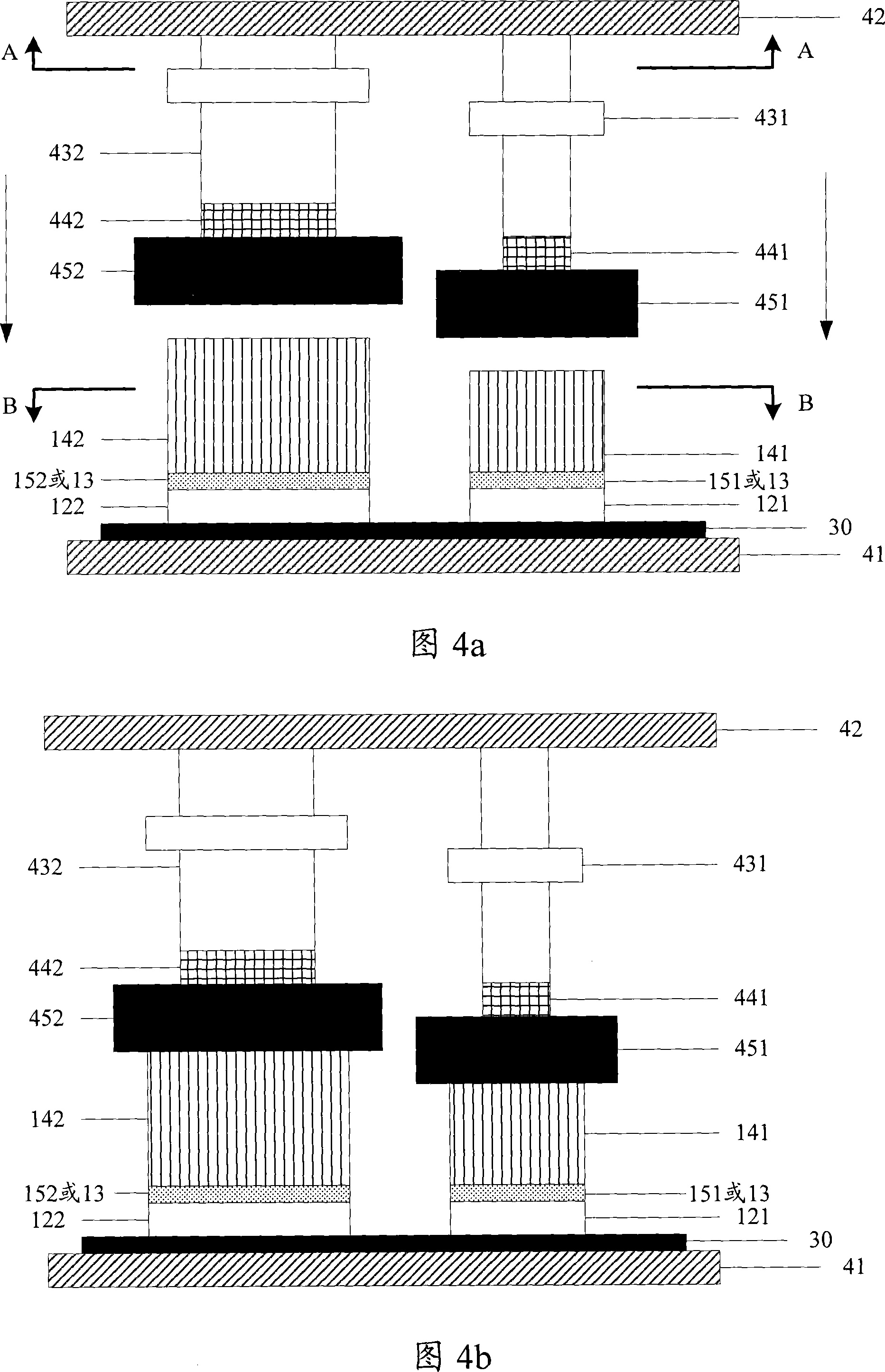
[0043] In this embodiment, a pressure component is set at the position corresponding to each installation position, and at least two parts to be installed that are stacked up and down and need to be bonded are placed on the installation position, and each The parts to be installed at the installation position apply pressure to realize the adhesive pressure installation of the parts to be installed.

[0044] Wherein, taking installing a heat sink on a PCB as an example, the installation position is predetermined according to the chip position on the PCB where the heat sink needs to be installed. Different PCBs or different chips that need to be installed with heat sinks correspond to different heat sink installation positions.

[0045] Fig. 2 is an exem...


PUM


Abstract

No need of manpower to take part in, the invention raises installing efficiency, and reduces possibility of physical damaging chip and heat sink. Under automatic control, movement-feeding structure (MFS) drives press set table (PST) to implement press installation. Being installed between MFS and PST, pressure sensor is capable of feeding magnitude of press in current installation procedure in real time so as to realize closed loop control for MFS as well as to raise precision of press, and guarantee reliability of press installation. Magnitude of press is dependent on displacement of PST driven by MFS and not by size of pressing block. Thus, lots of pressing block is not needed so as to save installation space and cost. Moreover, it is not possible to occur that pressing block with large weight is unable to be placed in limited space between chips so as to cause instance of installing failure. The invention increases practicability and generality of press installation.

Description

technical field [0001] The invention relates to assembly and installation technology in the field of electronic technology, in particular to a pressure mounting device and a pressure mounting method in the field of electronic technology. Background technique [0002] With the continuous development of electronic technology, a printed circuit board (Printed Circuit Board, PCB) for various purposes such as a single board becomes more and more complicated. For example, the layout density of PCB is higher, the number of chips is larger, and the power of chips is higher. [0003] For a chip with a large power consumption, it generates a large amount of heat when it is in operation, and it is often necessary to install a radiator on its surface to dissipate heat. [0004] The commonly used heat sink installation method is: use thermally conductive adhesive materials to bond the heat sink to the surface of the chip to ensure the stable bonding between the chip and the heat sink, a...

Claims


Application Information

Patent Timeline
IPC IPC(8): H05K13/04H05K13/08
Inventor 彭维萍孙小华
Owner NEW H3C TECH CO LTD
Learn More