Jet pump

A nozzle and channel technology, applied in jet pumps, pumps, non-displacement pumps, etc., can solve the problems of very sensitive position, blockage of coarse materials, unstable position of cold shock wave, etc., to achieve the effect of optimizing energy transfer

Inactive Publication Date: 2007-08-29
PURSUIT DYNAMICS
View PDF0 Cites 11 Cited by
  • Summary
  • Abstract
  • Description
  • Claims
  • Application Information

AI Technical Summary

Problems solved by technology

A major limitation of conventional converging / diverging systems is that their performance is very sensitive to the location of the cold shock, which is often unstable and easily deviates from the optimum position
It is known that if a cold shock wave forms in the wrong place in the converging / diverging section, the associated unit (device) will most likely stop working
In addition, such systems can only achieve cold shock waves in a limited area
[0005] In addition, for systems utilizing a central steam nozzle, throat size limitations and sharp directional changes affecting the working fluid present severe limitations on the size of the particulate throughput, and of course any coarse material that may enter the system may cause clogging

Method used


Image

  • Jet pump
  • Jet pump
  • Jet pump

Examples


Embodiment Construction

[0079] The same components are denoted by the same reference numerals in the specification.

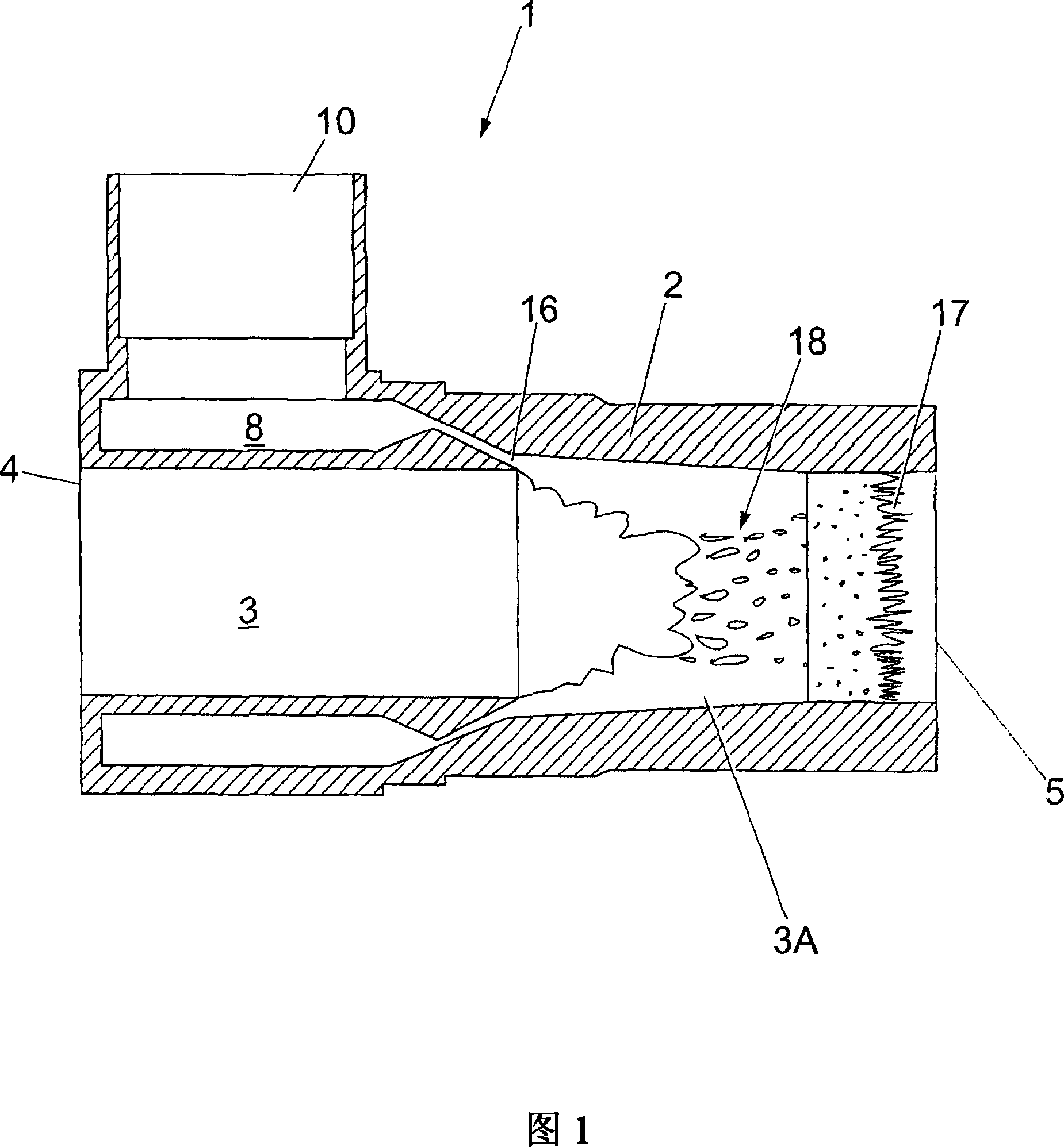
[0080] Referring to Figure 1 , there is shown a fluid mover 1 comprising a housing 2 defining a channel 3 providing an inlet 4 and an outlet 5, the channel 3 having a substantially constant circular cross-section.

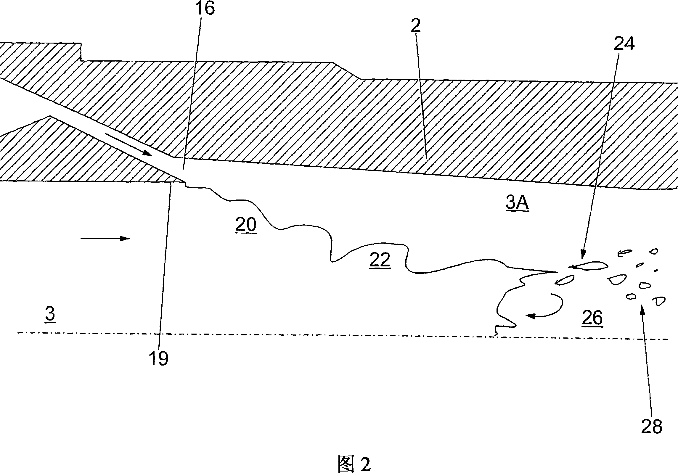
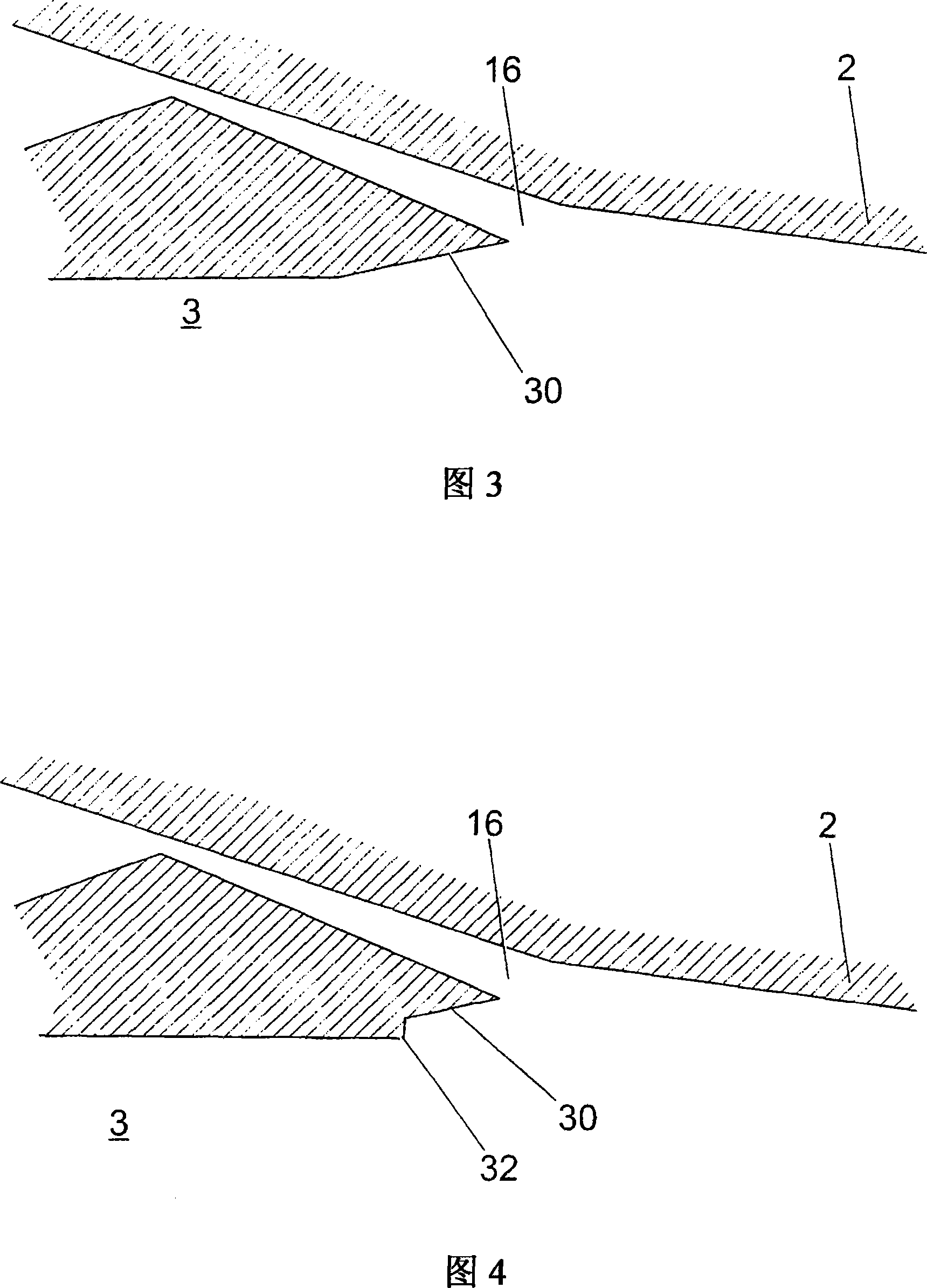
[0081] The housing 2 comprises a plenum 8 for introducing a carrier fluid, the plenum 8 being provided with an inlet 10 . The end of the plenum is tapered and defines an annular nozzle 16 . Nozzle 16 is in fluid communication with plenum 8 . The nozzle 16 is formed to produce a supersonic flow in use.

[0082] In operation, the inlet 4 is connected to a source of process or working fluid. Steam is introduced into the fluid mover 1 through the inlet 10 and the plenum 8 , causing a jet of steam to be ejected forward through the nozzle 16 . The steam ejected from the nozzle 16 interacts with the working fluid in the channel section serving as the mixing chamber (3A). In ...


PUM


Abstract

A fluid mover (1) includes a hollow body (2) provided with a straight-through passage (3) of substantially constant cross section with an inlet end (4) an outlet end (5) for the entry and discharge respectively of a working fluid. A nozzle (16) substantially circumscribes and opens into the passage (3) intermediate the inlet (4) and outlet (5) ends. An inlet (10) communicates with the nozzle (16) for the introduction of a transport fluid and a mixing chamber (3A) is formed within the passage (3) downstream of the nozzle (16). The nozzle internal geometry and the bore profile immediately upstream of the nozzle exit are disposed and configured to optimise the energy transfer between the transport fluid and working fluid. In use, through the introduction of transport fluid, the working fluid or fluids are atomised to form a dispersed vapour / droplet flow regime with locally supersonic flow conditions within a pseudo-vena contracta, resulting in the creation of a supersonic condensation shock wave (17) within the downstream mixing chamber (3A) by the condensation of the transport fluid. Methods of moving and processing fluids using the fluid mover are also disclosed.

Description

technical field [0001] The present invention relates to a method and apparatus for moving a fluid. Background technique [0002] The present invention relates to improvements to fluid movers of a large number of different types in applications ranging from marine propulsion systems to pumping for moving and / or mixing fluids and / or solids with the same or different properties practical application. The invention also relates to the fields of heating, cooking, cleaning, aeration, gas fluidization, and agitation of fluids and fluid / solid mixtures, particle separation, classification, disintegration, mixing, emulsification, homogenization, dispersion, immersion hydrolysis, hydration, atomization, droplet generation, viscosity reduction, dilution, shear thinning, transport of thixotropic fluids, and pasteurization. [0003] More particularly, the present invention relates to providing an improved fluid mover that is substantially free of moving parts. [0004] Eductors are wel...

Claims


Application Information

Patent Timeline
Patent Type & Authority Applications(China)
IPC IPC(8): F04F5/46F04F5/24
CPCY02E50/17Y02E50/16
Inventor 马库斯·布莱恩·梅哈尔·芬顿亚历山大·盖伊·沃利斯
Owner PURSUIT DYNAMICS
Why Eureka
Try Eureka