Permanent-magnetic clutch device

A clutch device, permanent magnet technology, applied in the main field of rotational force between driven shafts, engagement and separation, can solve the problems of slow engagement and separation speed, easy short circuit of the circuit, uneven engagement of friction plates, etc.

Inactive Publication Date: 2007-09-05
赵荣伟
View PDF2 Cites 16 Cited by
  • Summary
  • Abstract
  • Description
  • Claims
  • Application Information

AI Technical Summary

Problems solved by technology

The problems of the friction clutch are that the friction loss of the friction plate is large and the heat dissipation performance is poor, and the loss of the friction plate is very serious, and it is easy to slip, and the friction plate is not evenly joined and separated completely.
Mechanical, pneumatic, hydraulic, electromagnetic, centrifugal, overrunning, magneto-rheological fluid and other clutches have problems to varying degrees, such as energy consumption, no overload protection, and ci

Method used


Image

  • Permanent-magnetic clutch device
  • Permanent-magnetic clutch device
  • Permanent-magnetic clutch device

Examples


Embodiment 1

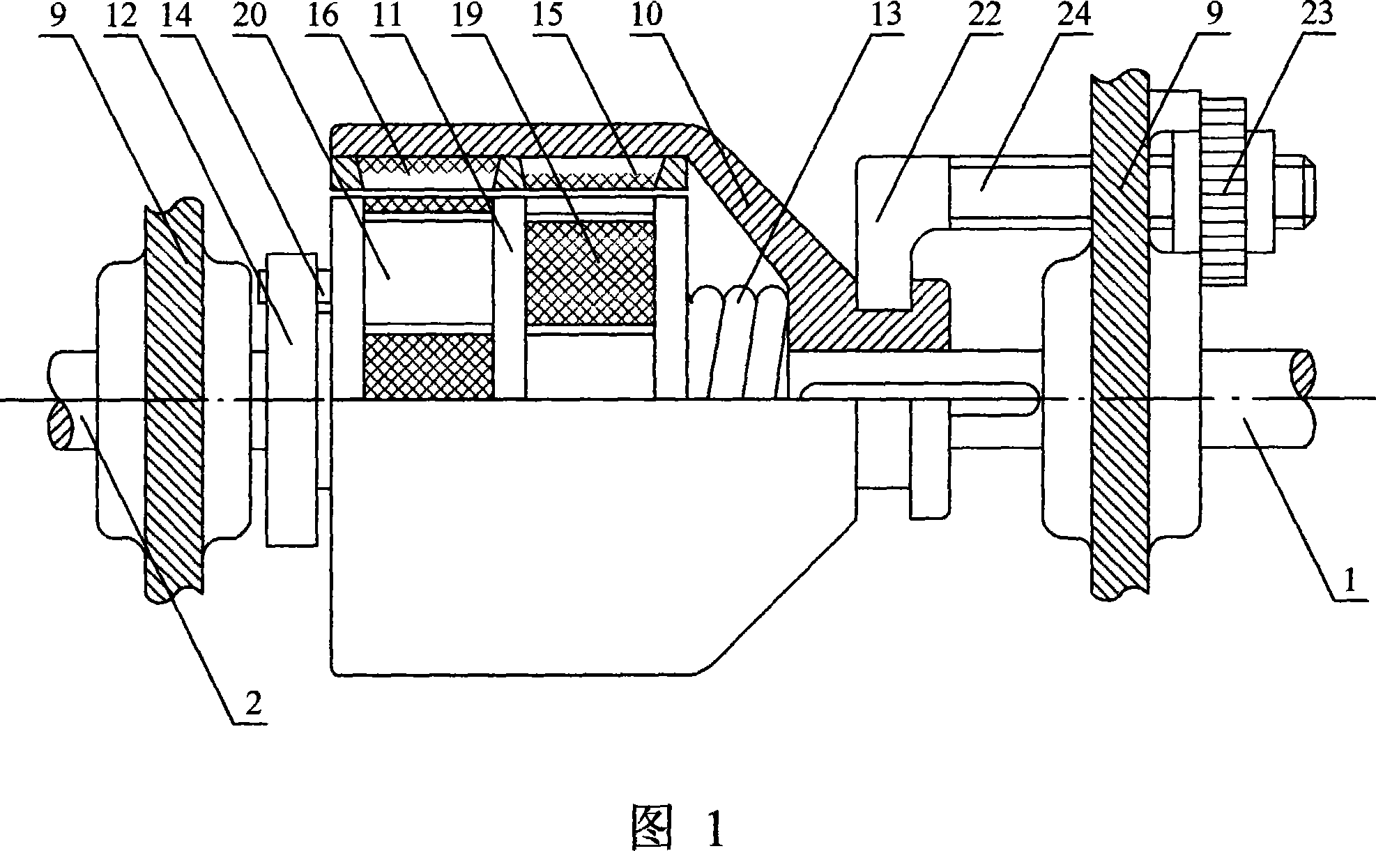
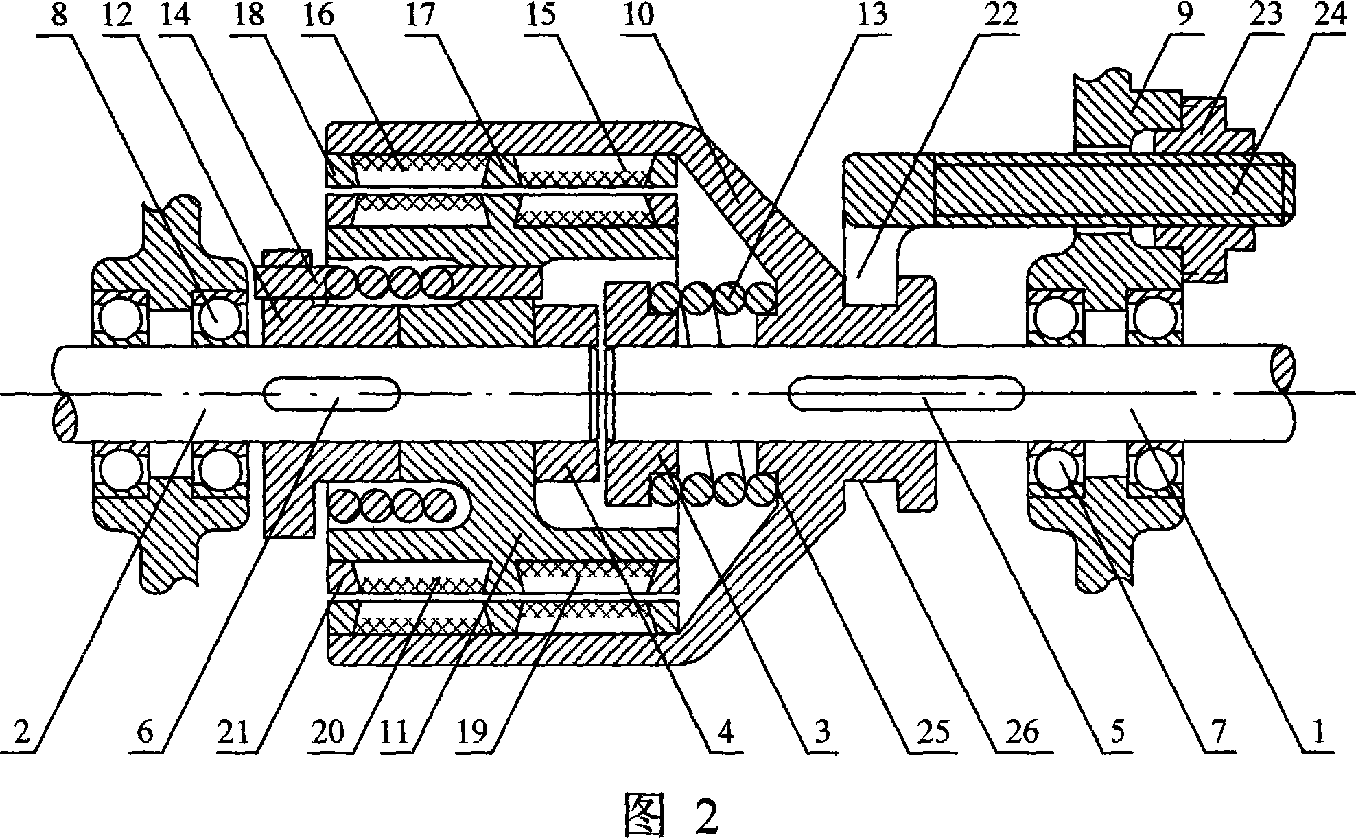
[0056]Embodiment 1: As shown in Figure 1-2, the driving shaft (1) and the driven shaft (2) of the present invention are aligned. The driving wheel (10) and the driving shaft (1) are guided by the driving shaft key (5) and can be connected for axial movement, and its moving distance is less than the axial length of a single magnetic block. The active inner and outer magnetic blocks (15, 16) are radially connected with the inner wall surface of the cylinder of the active wheel (10). The middle and side hoops (17, 18) of the active magnetic block press the magnetic block between the axial active inner and outer magnetic blocks (15, 16) and the edge respectively, and are tightly connected with the driving wheel disc (10). The section is trapezoidal. The active spring (13) is a helical compression spring. One axial end of the spring is placed on the active shaft cap (3), and the other end is placed on the spring groove (25) of the active wheel. The maximum compression force of the...

Embodiment 2

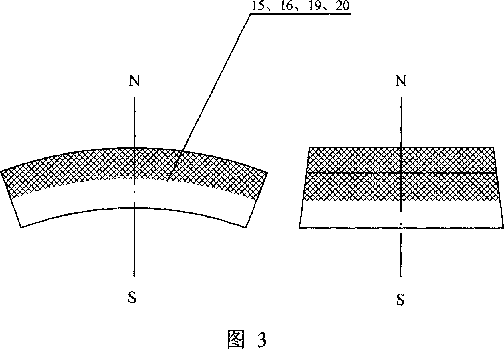
[0057] Embodiment 2: as shown in Figure 3, the main and driven inner and outer magnetic blocks (15, 16, 19, 20) of the present invention are permanent magnet tile-shaped structures, and the outer arc surface and inner arc surface direction of the magnetic block are south poles (S) The magnetization direction of the north pole (N), the arc direction section of the magnetic block is trapezoidal, and the trapezoidal direction of the active magnetic block and the driven magnetic block are in opposite directions. The magnetic block is made of high-performance permanent magnets, and made into a flat block shape to reduce the radial size of the device.

Embodiment 3

[0058] Embodiment 3: as shown in Figure 4, the inner circle of the control wheel (23) of the present invention is a thread, the outer circle is an axial straight line, the outer circle of the joystick (24) is a thread, and the rod head is formed into two pieces. The control dial (22) is fastened and connected, and the connection method can be bolts, rivets or welding. The control wheel (23) can be rotatably connected with the joystick (24), and the control dial (22) is made of non-ferromagnetic material. . Its working principle is: when the control wheel (23) rotates, the joystick (24) is moved axially, and the rotation can control its movement and counteract the axial impact force produced between the main and driven magnetic blocks.


PUM


Abstract

The invention is concerned with permanent-magnet clutch equipment, relating to main axis and driven axis, connecting with main and driven turntables, main and driven springs, axis-joining wheel, operate perch and wheel, bearing frame, main and driven inside and outside magnetism blocks. When the main axis is moving, the main and driven inner and outside magnetism blocks work through gas-gap magnetism induction action, and the magnetizations direction to south and north poles of the main and driven inner and outside magnetism blocks is the radial, the amount is same even and the south and north poles are opposite located towards to the middle to produce the attracting and excluding shear around the movement direction of axes between the main and driven magnetism blocks that moves in synchronous according to shear. The radial suction face and excluding power face is same between the main and driven magnetism blocks to balance the attracting and excluding shear along the movement direction of axes. The main and driven magnetism blocks do not drive the revolving and driving force, so the revolving and driving force can joint and separate with each other between the main and driven axes.

Description

technical field [0001] The invention relates to a device for engaging and separating rotational force between a main shaft and a driven shaft, especially a permanent magnet clutch device utilizing magnetic induction transmission. Background technique [0002] At present, known clutches are roughly classified into clutches such as friction type, mechanical type, pneumatic type, hydraulic type, electromagnetic type, centrifugal type, overrunning type, and magneto-rheological fluid. The friction clutch realizes transmission and stops transmission through friction plate engagement and friction plate separation. The problems of the friction clutch are that the friction loss of the friction plate is large and the heat dissipation performance is poor, and the loss of the friction plate is very serious, and it is very easy to slip, and the friction plate is not evenly joined and separated. Mechanical, pneumatic, hydraulic, electromagnetic, centrifugal, overrunning, magneto-rheologi...

Claims


Application Information

Patent Timeline
IPC IPC(8): H02K49/10
Inventor 赵荣伟
Owner 赵荣伟
Why Eureka
Try Eureka