Pipe leakage detecting instrument, detecting device and detecting method based on dynamic low-frequency technology

A technology of pipeline leakage and detector, which is applied in pipeline systems, mechanical equipment, gas/liquid distribution and storage, etc., can solve the problems of short response time, reduced output data attenuation, inability to distinguish leaking sonic signals, etc., and achieve accurate judgment. , the effect of improving the accuracy

Inactive Publication Date: 2007-09-12
陆国良
View PDF2 Cites 27 Cited by
  • Summary
  • Abstract
  • Description
  • Claims
  • Application Information

AI Technical Summary

Problems solved by technology

Since the accuracy of the output value is guaranteed under the static working state, that is, the response time is long, the accuracy of the pressure change under the dynamic working state, that is, the response time is short, especially for small pressure changes. inability to measure accurately
However, from the basic nature of pipeline leakage, it can be seen that pipeline leakage is an instantaneous dynamic change, not only the response time is short, but also the pressure change is very small, so the pressure transmitter in the prior art cannot convert a small transient pressure The instrument output at which the variation reaches the maximum affects the correct judgment of pipeline leakage and causes false alarms
[0008] Most of the pipeline leakage occurs at least a few kilometers away from the first statio

Method used


Image

  • Pipe leakage detecting instrument, detecting device and detecting method based on dynamic low-frequency technology
  • Pipe leakage detecting instrument, detecting device and detecting method based on dynamic low-frequency technology
  • Pipe leakage detecting instrument, detecting device and detecting method based on dynamic low-frequency technology

Examples


Embodiment 1

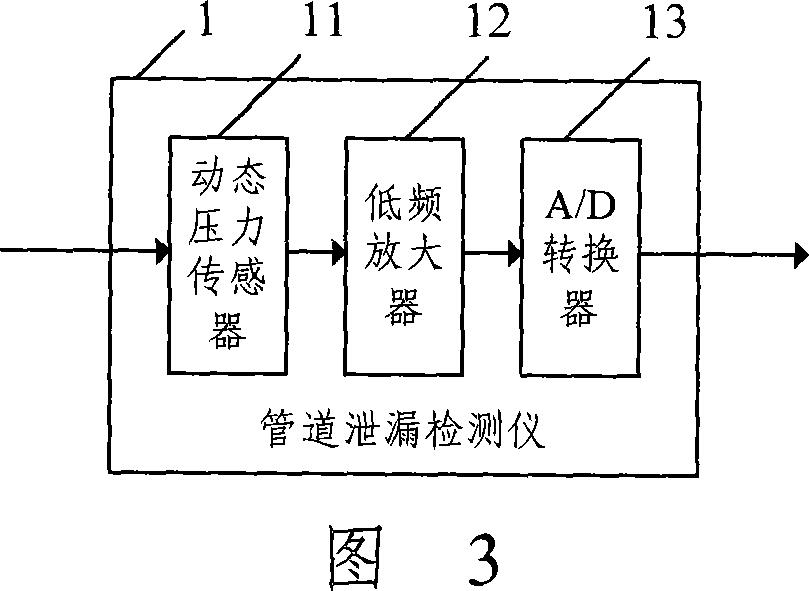
[0055] Based on the principle of Fig. 3, the dynamic pressure sensor 11 is connected with the A / D converter 13 through the low-frequency amplifier 12, and the dynamic pressure sensor 11, the low-frequency amplifier 12 and the A / D converter 13 adopted are specifically:

[0056] The dynamic pressure sensor 11 used has a working frequency range of 0-1000 Hz, and the rise time, that is, the response time is greater than 2 μs. The response time of the dynamic pressure sensor 11 is greater than 2 μs, which ensures the dynamic response of the dynamic pressure sensor 11.

[0057] The low-frequency amplifier 12 matched with the dynamic pressure sensor 11 collects low-frequency data signals, adjusts the measurement range with multiple gears, and adjusts the measurement range of the pipeline leak detector 1 according to the dynamic pressure change in pipeline operation, and adopts a full scale of 0-5V output, the measured frequency range is below 20Hz.

[0058] The selection requirement ...

Embodiment 2

[0064] As shown in Figure 6, a pipeline leak detection device based on dynamic low-frequency technology includes two pipeline leak detectors 1a and 1b, two base stations 2a and 2b, a central control station 3, and three GPS locators 4a and 4b and 4c.

[0065] The pipeline leak detectors are installed at the first station of the pipeline and the last station of the pipeline, respectively, the pipeline leak detector 1a at the first station of the pipeline and the pipeline leak detector 1b at the last station;

[0066] The pipeline leakage detector 1a at the first station of transportation is connected to the central control station 3 through the first base station 2a, the pipeline leakage detector 1b at the last station of transportation is connected to the central control station 3 through the second base station 2b, and the first base station 2a is connected to the central control station 3 to carry out remote communication to detect the output value of the pipeline leakage de...

Embodiment 3

[0075] A certain pipeline has a total length of 100.3km, the operating pressure of the first station is 2.2Mpa, the operating pressure of the last station is 0.25Mpa, the amount of oil and gas transported is 220m3 / h, and the diameter of the pipeline is 426mm.

[0076] Based on the principle of Figure 7, this embodiment adopts the pipeline leak detector shown in Figure 3 and the pipeline leak detection device shown in Figure 6, the full scale of the pipeline leak detector is 5000mV, a pipeline leak detection based on dynamic low frequency technology method, including the following steps:

[0077] Step 201: through the dynamic response of the dynamic pressure sensor 11 in the pipeline leakage detector 1 to the dynamic pressure variation, and the low-frequency amplifier 12 matched with it, the low-frequency pipeline leakage sound wave signal is collected, and the signal is converted by the A / D converter 13; The leak detector 1 includes a pipeline leak detector 1a at the first del...


PUM


Abstract

The invention discloses a kind of conduit leakage detecting instrument, a detecting device and the method which base on the dynamic low-frequency technology. The conduit leakage detecting instrument includes a dynamic pressure sensor; the detecting device includes a conduit leakage detecting instrument, a base station, a central control station, and a GPS locating instrument and the conduit leakage detecting instrument connects with the central control station though the base station and the base station and the central station set up a locating instrument; the detecting method includes the following steps: the central station sets up the dynamic adjustable measuring range of the conduit leakage detecting instrument according to the get dynamic pressure variety; the GPS locating instrument can gets the time of the conduit leakage acoustic wave arriving the delivery first station or the delivery last station's conduit leakage detecting instrument individually; it can get the location of conduit leakage by plus-minus the time told above then multiply the transmission speed of the acoustic wave in the medium. It improves the measurement precision of the smaller pressure variety by adopting the detecting instrument and the detecting device and the method of the invention also can separate the leakage acoustic signal so it can determine the location of conduit leakage correctly.

Description

technical field [0001] The invention relates to pipeline leakage detection technology, in particular to a pipeline leakage detector, detection device and detection method based on dynamic low-frequency technology. Background technique [0002] Oil and gas pipelines are composed of pipelines connecting pressurization stations, distribution stations, blending stations, heating stations and pigging stations. Measuring instruments such as flow transmitters, pressure transmitters, and temperature transmitters are used to detect pipeline leaks. The method for judging pipeline leakage disclosed in the earlier Chinese invention patent Nos. 9612100.1 and 99107241.3 is to install multiple measuring instruments such as flow transmitters, pressure transmitters, and temperature transmitters at each of the above-mentioned stations, and according to From the data collected by the plurality of measuring instruments, it is judged whether the pipeline is leaking. [0003] The document with ...

Claims


Application Information

Patent Timeline
IPC IPC(8): F17D5/06
Inventor 陆国良
Owner 陆国良
Why Eureka
Try Eureka