Method and apparatus for bending

A bending processing and bending technology is applied in the field of bending processing and its devices to achieve the effects of improving processing efficiency, reducing burden and preventing defective products

Active Publication Date: 2007-09-12
AMADA CO LTD
View PDF1 Cites 14 Cited by
  • Summary
  • Abstract
  • Description
  • Claims
  • Application Information

AI Technical Summary

Problems solved by technology

[0025] However, in the case where the workpiece supporting member 3 is provided to prevent the workpiece from sagging when the workpiece is abutted (FIG. 34(A) of the present application), when the workpiece W must be positioned against the workpiece supporting member 3 When ((Fig. 34(B) of the present application), from a structural point of view, the conventional contact confirmation sensor cannot normally play its role

Method used


Image

  • Method and apparatus for bending
  • Method and apparatus for bending
  • Method and apparatus for bending

Examples


Embodiment Construction

[0089] Hereinafter, the present invention will be described in terms of embodiments with reference to the drawings.

[0090] A. The first invention

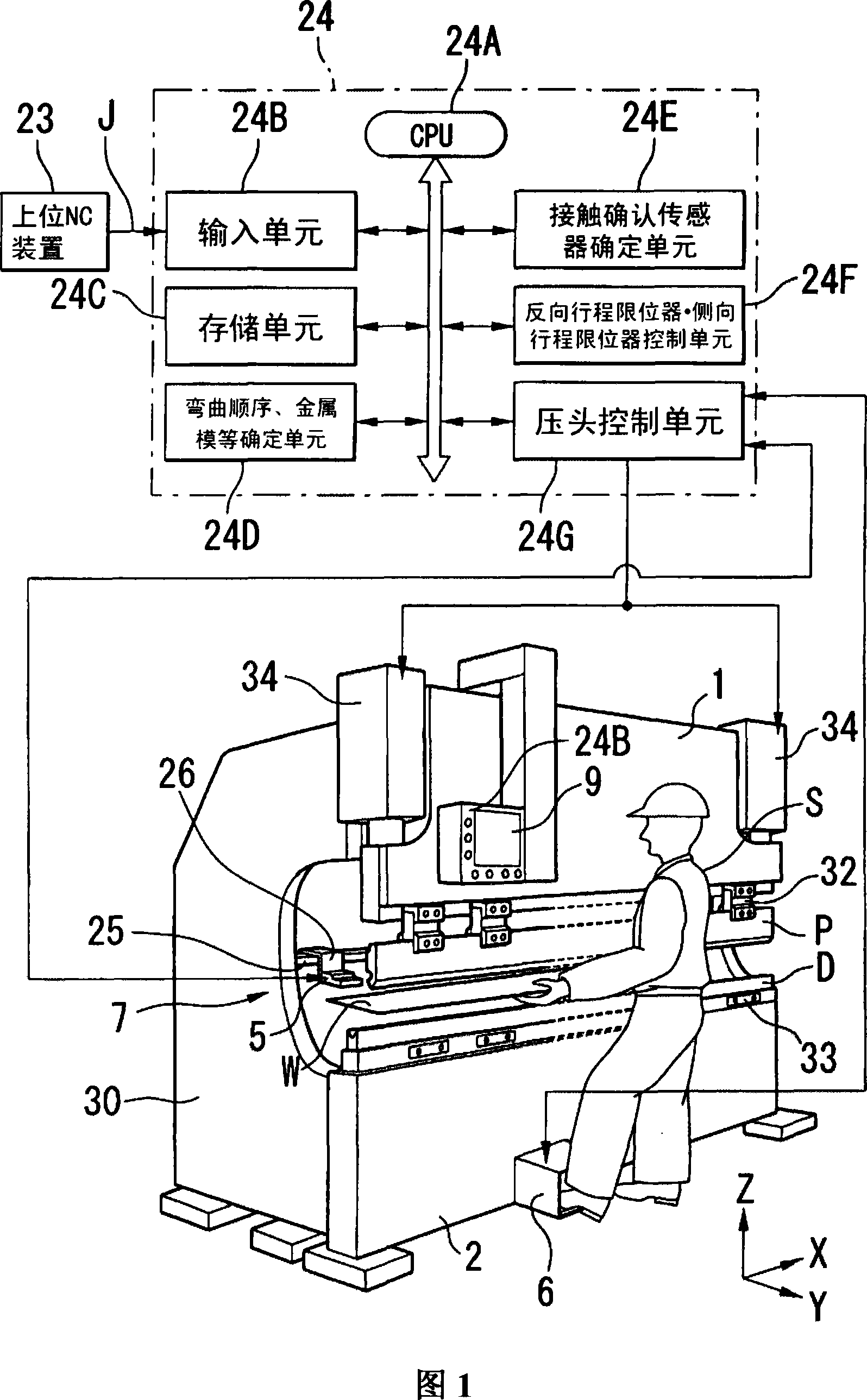
[0091] FIG. 1 shows an embodiment of the first invention of the present invention, and the illustrated bending device is, for example, a plate bender.

[0092] The bending machine is provided with side plates 30 on both sides of the machine body. On the top of the side plates 30, an upper workbench 1 as a pressure head is installed through, for example, a hydraulic cylinder 34. On the upper workbench 1, pass through the middle The plate 32 is fitted with punches P.

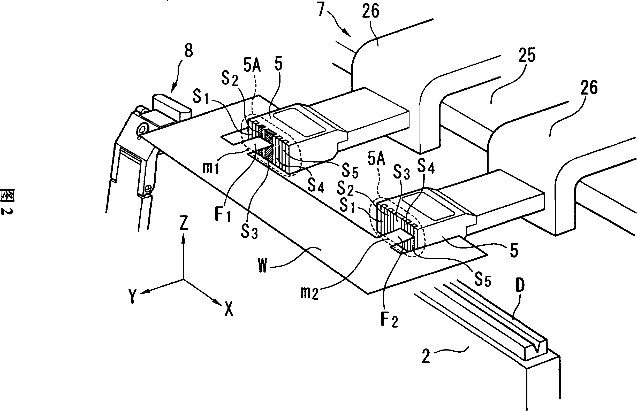
[0093] In addition, the lower table 2 is disposed under the side plate 30, and the mold D is attached to the lower table 2 through the holding plate 33. At the same time, a side table 2 is freely movable in the left-right direction (X-axis direction). The stroke stopper 8 ( FIG. 2 ) positions the workpiece W in the left-right direction.

[0094] That is, the bendi...


PUM


Abstract

In a bending machine, there is provided at one back gauge abutting part (5) a plurality of contact confirmation sensors for confirming the contact thereof with a workpiece; and there is included control means driving a ram (1) on the conditions of ON of all the sensors automatically or manually specified among these contact confirmation sensors and ON of a foot pedal (6) when the workpiece is abutted.A method and an apparatus for bending. The apparatus comprises, at a back gauge abutting part (5), a plurality of contact confirmation sensors for confirming the contact thereof with a work. The apparatus also comprises a control means which, when the work abuts on the back gauge abutting part, drives a ram (1) under the conditions that all automatically or manually specified sensors among the contact confirmation sensors are turned on and a foot pedal (6) is turned on.

Description

technical field [0001] The present invention relates to a bending process method and a device thereof when a contact confirmation sensor for confirming a contact state with a workpiece is provided on a contact portion of a reverse travel stopper. Background technique [0002] (1) Topic 1 [0003] In the past, in the plate bending machine, a workpiece positioning device as disclosed in JP-A-5-7938 is provided. The workpiece positioning device has a sensor at the center of the abutment surface of the reverse stroke limiter and sensors on both sides of the abutment surface. electromagnet. [0004] With this structure, when the workpiece is in contact with the sensor, the workpiece is attracted and fixed due to the excitation of the electromagnet, so after that, the pressing head is driven, and the punch approaches the die. When the punch contacts the workpiece (punching point), the electromagnet demagnetizes, releases the workpiece, and performs a given bending process on the...

Claims


Application Information

Patent Timeline
IPC IPC(8): B21D5/02
Inventor 池田英胜
Owner AMADA CO LTD
Why Eureka
Try Eureka