
Scale-factor stabilised solid-state laser gyroscope

A technology of laser gyroscope and scale factor, which is applied in the direction of Sagnac effect gyroscope, etc., can solve the problems of inapplicability, different frequency of protection radiation mode, etc.

Inactive Publication Date: 2007-09-12
THALES TOUR CARPE DIEM PLACE DES COROLLES ESPLANADE NORD COURBEVOIE
View PDF1 Cites 5 Cited by
  • Summary
  • Abstract
  • Description
  • Claims
  • Application Information

AI Technical Summary

Problems solved by technology

[0021] This relationship does not apply when it represents a change in the compensation scale factor, which is a different problem than protecting the radiation mode frequency
In particular, there may be radiative mode hopping while preserving the scale factor

Method used


Image

  • Scale-factor stabilised solid-state laser gyroscope
  • Scale-factor stabilised solid-state laser gyroscope
  • Scale-factor stabilised solid-state laser gyroscope

Examples


Embodiment Construction

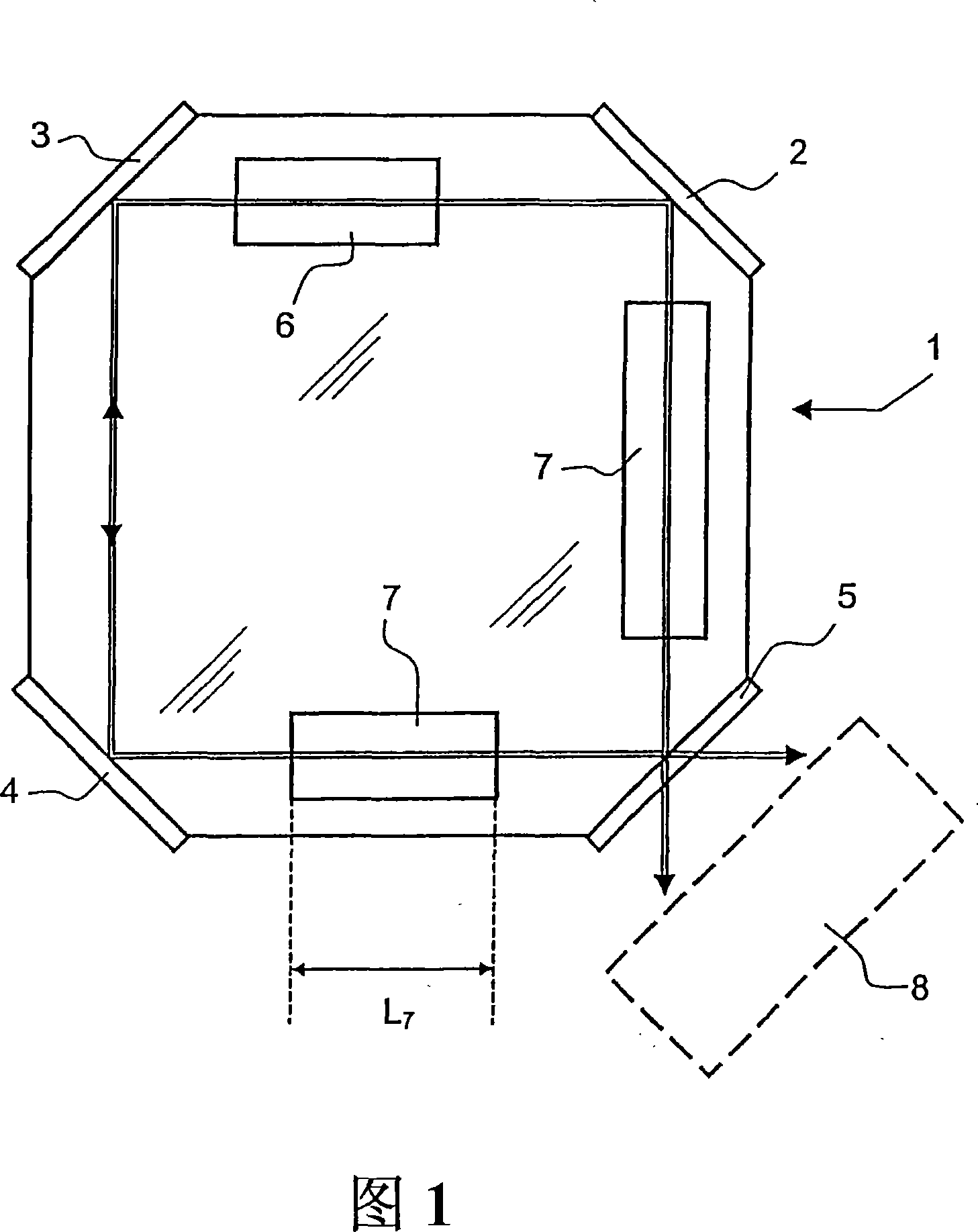
[0034] Fig. 1 shows a basic diagram of a laser gyroscope according to the invention. it includes:

[0035] the cavity 1 is made of a first material and comprises several mirrors 2, 3 and 4, and a partial mirror 5;

[0036] Amplifying medium 6;

[0037] · at least one optical element 7 of length L7;

[0038] • The overall assembly is designed so that two optical waves can propagate in two opposite directions within the cavity. These two waves are represented in Figure 1 by double lines. These waves pass through different optical elements arranged inside the cavity.

[0039] and an opto-electronic measurement (an opto-electronic measurement) indicated by a dot-dash line, making it possible to calculate angular parameters based on measurements based on the interference pattern of two counter-propagating waves coming from the partially reflective mirror 5 .

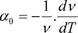
[0040] As mentioned above, the scale factor S of the laser gyroscope with the same as the previous note satisfies S = ...


PUM


Abstract

The invention relates to solid-state laser gyroscopes for measuring rotational speeds or angular positions which are used, in particular for aircraft engineering. A gyroscope performances depend on the temperature stability of the scale factor thereof (S) which is 4A / L, wherein L and A are the optical length and the area of the laser cavity, respectively and is a laser emission mean wavelength without the Sagnac effect. Conventionally, for gas lasers, each parameter of the scale factor is selected in such a way that it is temperature independent. The solid state lasers which are very different from the gas lasers are not treatable in the same manner. Said invention offers the laser cavity optical architecture based on the scale factor global conservation, wherein each parameter is temperature variable. An architecture which makes it possible to avoid optical mode hopes and several digital examples proving that inventive principles are applicable to standard materials are also disclosed.

Description

technical field [0001] The field of the invention relates to solid state laser gyroscopes for measuring rotational velocity and angular position. This instrument is used in particular for aerospace applications. Background technique [0002] Laser gyroscopes, developed about thirty years ago, now have a wide range of markets and applications. Its working principle is based on the Sagnac effect, consisting of a frequency difference Ω between two optical emission modes propagating in opposite directions, also known as under rotational drive Counterpropagating modes of a bidirectional ring laser cavity. The traditional frequency difference Ω satisfies: [0003] [0004] where S=4A / λ·L [0005] Among them, S is called the scaling factor of the laser gyroscope. L and A are called the optical length and area of ​​the laser cavity, respectively, λ is the average wavelength of the laser radiation without the Sagnac effect, and is the angular rotation speed of the laser gyr...

Claims


Application Information

Patent Timeline
IPC IPC(8): G01C19/66
CPCG01C19/66
Inventor G·弗加内特S·施瓦兹J-P·波绍利C·克里斯蒂安F·古提
Owner THALES TOUR CARPE DIEM PLACE DES COROLLES ESPLANADE NORD COURBEVOIE
Learn More