Conjuncted squat closet

A squatting pan and conjoined technology, which is applied to the field of toilet sanitary ware flushing equipment, can solve the problems of increasing the shape of the squatting pan, reducing the height of the squatting basin, and flowing into the skirt, and achieving the effects of reducing materials, reducing volume and novel shape

Inactive Publication Date: 2011-04-27
关云龙
View PDF1 Cites 0 Cited by
  • Summary
  • Abstract
  • Description
  • Claims
  • Application Information

AI Technical Summary

Problems solved by technology

But the problem that is easy to arise is: the setting of the front drainage pipe, the outlet of the siphon water-sealed elbow bends upwards from the lower end of the squatting basin, then bends upwards to the outer side, and then bends downwards to the longitudinal centerline of the squatting basin. The space between the bottom and the ground can only be provided with a single-diameter drainage pipe to reduce the height of the squatting basin, so that the drainage outlet of the squatting basin and the outlet of the drainage pipe are on the same center line, and only 30 cm and 40 cm drainage outlets can be installed. The 58 cm drainage outlet collides with the drainage outlet at the lower end of the squatting basin, so it cannot be installed
There is a new breakthrough in raising the floor to the ground compared with the traditional form, but the problem that is likely to arise is: because the manufacturing of sanitary ware is limited by the grouting molding of the ceramic process, the original square water circle and the skirt body must be separated on the upper plane to form a A barrier, about 1 cm thick, to prevent water from flowing into the skirt when the hydrosphere flushes
Since the skirt body is arranged in a plane on the outside of the square water circle, it can only be set so that the skirt body of the squatting pan is small at the top and large at the bottom due to the reason of untouching, so that the shape of the squatting pan increases, which affects the appearance and is not conducive to production

Method used


Image

  • Conjuncted squat closet
  • Conjuncted squat closet
  • Conjuncted squat closet

Examples


Embodiment 1

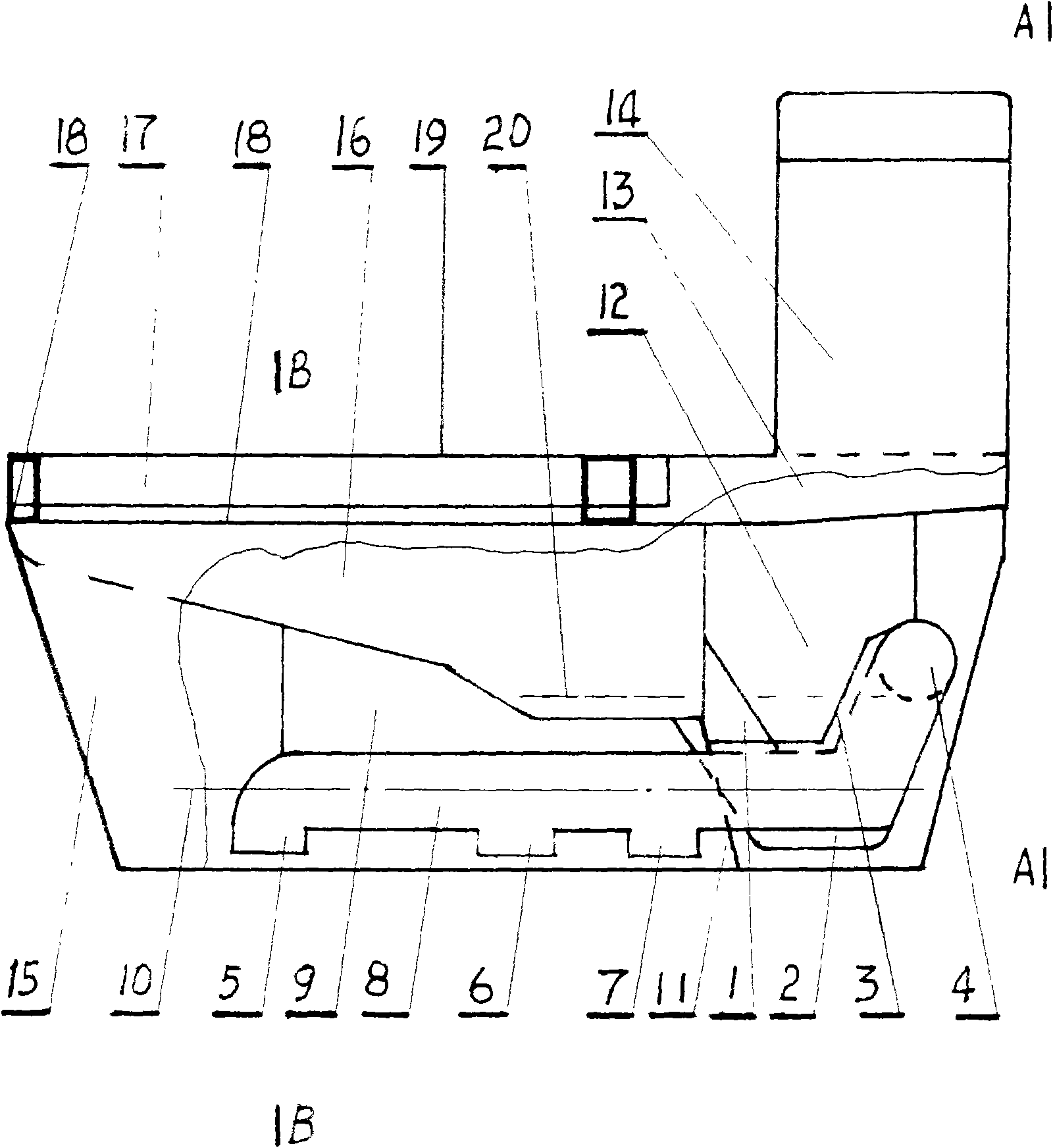
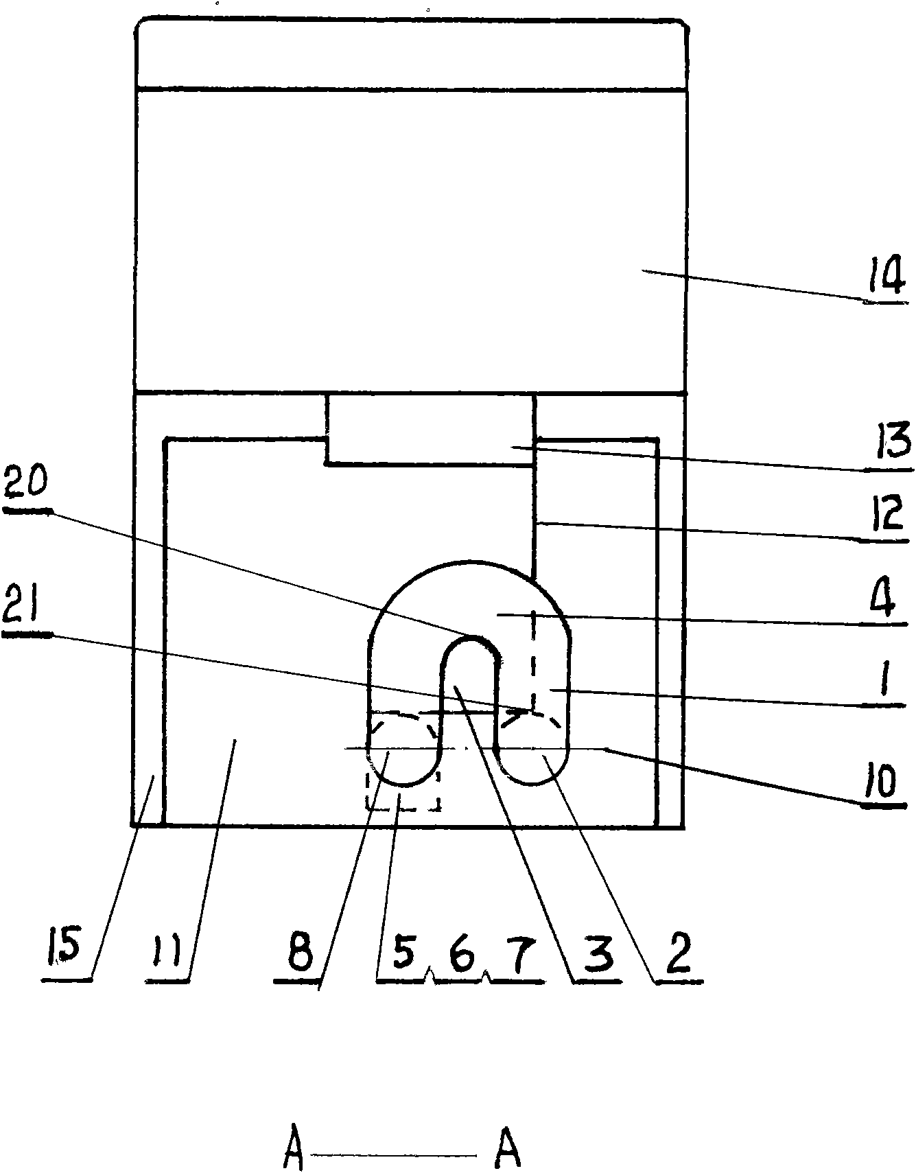
[0028] Embodiment 1: the conjoined squatting pan includes a squatting basin (16) seat above the squatting basin skirt body (15), and the squatting basin hydrosphere (17) rear end communicates with the water tank waterway (13) water tank (14). according to Figure 5 As shown in the schematic diagram of the sectional structure of the squatting basin pedal and the isolation belt in the prior art, a siphon type drainpipe (1) is arranged at the rear end of the squatting basin (16), including a V-shaped water-sealed lower bend (2) and a water-sealed transverse bend ( 4), drain main pipe (8), drain outlet (5), (6), (7).

[0029] Such as figure 1 As shown in the schematic diagram of the side sectional structure of the conjoined squatting pan, the structural form of the squatting pan (16) and the siphon drainpipe (1) is set as the structural form in which the conjoined squatting pan is only provided with the siphon drainpipe (1).

[0030] The V-shaped water-seal lower bend (2)-end is...

Embodiment 2

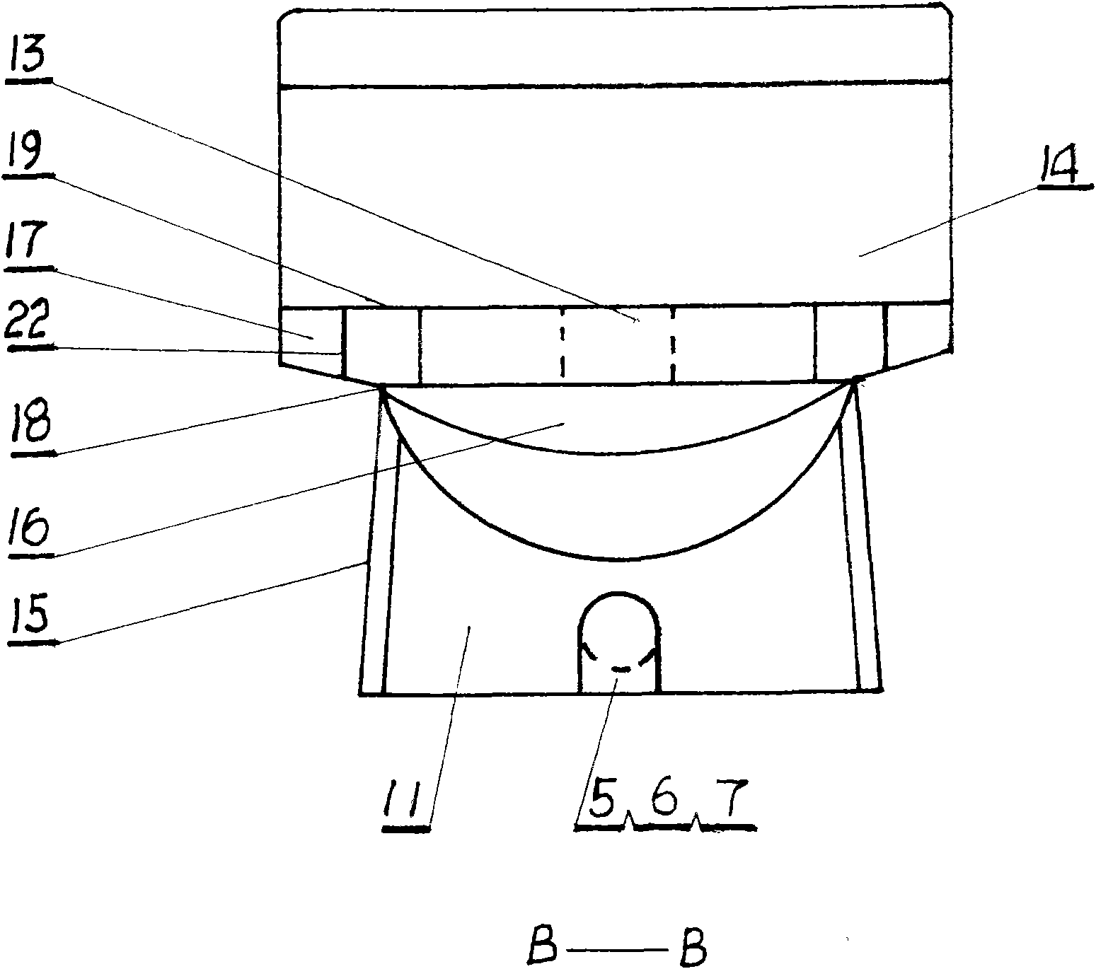
[0032]Embodiment 2: the conjoined squatting pan includes a squatting basin (16) seat on the squatting basin skirt body (15), and the squatting basin hydrosphere (17) rear end is communicated with the water tank waterway (13) water tank (14). according to Figure 5 As shown in the schematic diagram of the sectional structure of the squatting basin pedal and the isolation belt in the prior art, the squatting basin water circle (17) is set as a flat form, the upper surface is set as the plane of the squatting basin pedal (19), and the outer surface of the squatting basin skirt body (15) is in contact with the Squatting basin (16) upper edge mouth place and squatting basin hydrosphere (17) lower end middle position joint structure, in three-dimensional structure form, the thickness of its handover point is about 1 centimeter and is established as isolation zone (18), isolation zone (18 ) is extended to the rear end of the squatting basin (16) along both sides of the lower end of t...

Embodiment 3

[0034] Embodiment 3: Add embodiment 2 on the basis of embodiment 1. Such as figure 1 figure 2 image 3 Merge implementation shown. Embodiment 1, embodiment 2, make conjoined squatting pan obtain more complete improvement technology.

[0035] Figure 4 Schematic diagram of the improved structure of the squatting pan pedal in the B-B section of the conjoined squatting pan. In embodiment 2 embodiment 3, squat basin pedal (19) according to Figure 4 Improvements can be made. Reinforcement plate (22) is strip plate shape according to the left side figure, is located at the longitudinal center position in the water circle (17) of squatting basin, plays support reinforcement effect. The number is evenly distributed 2-3. Make a downward groove on the outer edge of the lower end of the squatting basin water circle (17) according to the outer groove (23) of the right side figure. Length is less than the length of squatting basin pedal (19).

[0036] The used material of embod...


PUM


Abstract

The invention belongs to the sanitaryware flushing apparatus field. A conjoined pan comprises a squatting pan (16) arranged above a squatting pan skirt (15), a squatting pan water cycle (17) with a rear end communicating with a water tank. Wherein, the rear end of the squatting pan (16) is provided with a siphon drainage pipe (1) comprising an V-type water seal down siphon (2) which is bent downward to lower the down flowing water surface of the water seal, communicate with the upper flowing water surface of the water seal transverse siphon (4), and smoothly connects to a main drainage pipe (8), the main drainage pipe (8) is provided with drainage outlet (5), (6) and (7). The lower pipe center of the V-type water seal down siphon (4) and the main drainage pipe (8) are juxtaposedly arranged on a same horizontal central line, and a horizontal rib plate (3), a longitudinal rib plate (9) and a vertical rib plate (12) configure are assembled with the squatting pan (16). The squatting pan water cycle (17) is flat-pipe like, the upper surface of the squatting pan water cycle (17) is provided with a squatting pan pedal (19), and the lower middle part of the squatting pan water cycle (17) is assembled with the external side of the squatting pan skirt (15) and the edge of the squatting pan (16), and the joint of the three parts is about 1cm thick, shows a stereoscopic structure form andis arranged into an isolation area (8) to reduce the bulk of the squatting pan skirt (15). The siphon type drainage pipe (1) allows the squatting pan (16) to have a siphon function and the main body to be lowered to a suitable height.

Description

Technical field: [0001] The invention belongs to toilet sanitary ware flushing equipment and relates to a conjoined squatting pan. Background technique: [0002] In the known technology, the basic form of the squatting toilet is that the upper edge of the squatting toilet is level with the ground, and the whole body is placed below the ground. The drain outlet of the squatting basin drains water in a straight-through or flushing manner. Patented technology No. ZL200520117556.5, a new combined toilet discloses a sanitary appliance that can be easily converted between a sitting basin and a squatting basin. The main structure of the squatting basin is similar to The "combined squatting toilet" that can be placed above the ground has a new breakthrough in the structural form of the squatting basin drain pipe and squatting basin pedal. But the problem that is easy to arise is: the setting of the front drainage pipe, the outlet of the siphon water-sealed elbow bends upwards from ...

Claims


Application Information

Patent Timeline
Patent Type & Authority Patents(China)
IPC IPC(8): E03D1/28E03D11/13
Inventor 关云龙
Owner 关云龙
Why Eureka
Try Eureka