
Roof modified constitution of flat building and construction method

A technology for buildings and flat roofs, which is applied to building structures, building components, roofs, etc. It can solve problems such as poor construction, lack of vertical load, and endurance problems, and achieve good waterproof effects

Inactive Publication Date: 2007-09-19
SEKISUI CHEM CO LTD +1
View PDF1 Cites 9 Cited by
  • Summary
  • Abstract
  • Description
  • Claims
  • Application Information

AI Technical Summary

Problems solved by technology

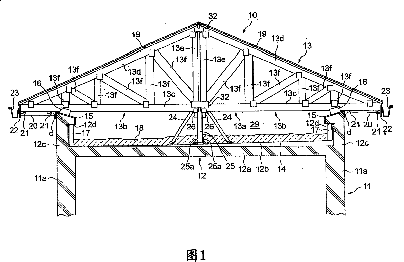
[0010] However, the above-mentioned conventional flat roof reconstruction structure is a structure in which the new roof is supported only by the legs 8 and the pedestal 9 on the flat roof 1a, and therefore, the load imposed on the flat roof 1a by the new roof is caused. Concentrated on the legs 8 and the pedestal 9 on the flat top 1a, there is a problem in terms of endurance
[0011] Furthermore, there is a problem that the existing flat-roofed buildings do not have the endurance to support the vertical load imposed by the new roof on the slab portion that becomes the roof surface.
[0014] However, since the parapet part does not have the endurance to support the horizontal force applied to the horizontal direction by the new roof, it is necessary to strengthen the parapet part itself or install new beams on the flat roof, so there is a problem with construction. Poor and cost-increasing problems

Method used


Image

  • Roof modified constitution of flat building and construction method
  • Roof modified constitution of flat building and construction method
  • Roof modified constitution of flat building and construction method

Examples


Embodiment 1

[0151] In the above-described embodiment, the new roof 13 is arranged on the flat roof 12 of the existing building 11 having the retaining wall portions 12c, 12c, but it is not limited thereto. As shown in FIG. The roof reconstruction structure 100 in which the new roof 13 is placed on the flat roof 120 of the existing building 110 formed with the eaves 120c, 120c.

[0152] In this roof reconstruction structure 100 , the eaves 120c, 120c extend horizontally from the outer walls 110a, 110a toward the outside at both edge portions of the flat roof 120 of the existing building 110 .

[0153] On the flat roof 120 of the existing building 110 having such a structure, the new roof 13 is arranged on the roof plate 120a surface of the flat roof 120 .

[0154] Moreover, the lower horizontal beams 13c, 13c of the partial truss structures 13b, 13b, which are the skeleton structure of the newly installed roof 13, are connected by the connecting member 160, ... Connect with flat top 120. ...

Embodiment 2

[0172] In the above-described embodiment, the parapet parts 12c, 12c of the flat roof 12 and the lower horizontal beams 13c, 13c of the new roof 13 are connected only by the parapet fittings 16, 16, but it is not limited thereto, as shown in FIG. 11 As shown, a roof reconstruction structure 200 may be provided in which a parapet fitting 224 as a connecting support member is installed between the newly installed roof 13 and the parapet portion 12c.

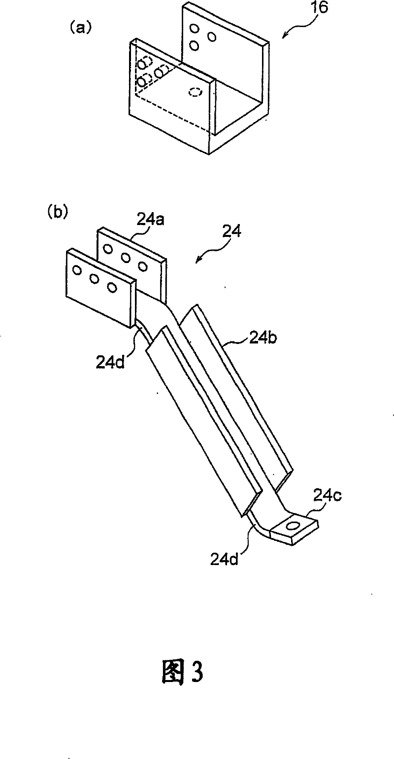
[0173] The shape of this parapet fitting 224 is substantially the same as that of the truss support fitting 24 of the above-mentioned embodiment, and is composed of an upper fixed end 224a, an inclined portion 224b, and a lower fixed end 224c.

[0174] The bottom surface of the upper fixed end 224a is fixed to the top surface of the protective wall portion 12c with the waterproof layer 15 interposed therebetween.

[0175] Further, the plate-shaped side walls extending upward from both sides of the bottom surface of the upper fixed ...

Embodiment 3

[0179]The truss support fittings 24, 24 serving as inclined members in the above-mentioned embodiment respectively support part of the truss structures 13b, 13b, but as shown in FIG. Both 13c and 13c are substantially parabolic truss support fittings 324 .

[0180] The upper fixed end 324a of the truss support fitting 324 is fixed so as to straddle the respective inner edge portions in the longitudinal direction of the lower horizontal beams 13c, 13c.

[0181] Therefore, since the lower horizontal beams 13c, 13c are connected to each other by the upper fixed end 324a, it is not necessary to separately use a connecting plate to connect the partial truss structures 13b, 13b to each other as in the above-mentioned embodiment, thereby improving the workability.


PUM


Abstract

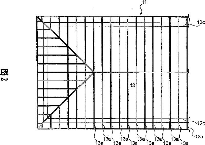
The invention provides a roof improved structure for flat-top building and a method for improving roof, which can form an improved structure which restrains the original burden on the flat top building to minimum and can reduce construction period and cost. The roof improved structure of the flat top building is formed by: arranging new designed roof (13) covered with flat top (12) on flat top, wherein the new designed roof (13) is formed by a skeleton construction with lower horizontal beams (13c, 13c).Protecting wall members (16, 16) for connecting and fixing the new designed roof (13) is arranged on protecting wall portions (12c, 12c) which protrude upwards along outer wall (11a, 11a) of the building (11).truss support members (24, 24) for limiting the lower horizontal beams (13c, 13c) moving in horizontal direction is arranged on the flat top (12).

Description

technical field [0001] The present invention relates to a roof reconstruction structure and a construction method of a flat-roofed building in which a new roof is provided on the flat roof of the building. Background technique [0002] Previously, sheet waterproofing or asphalt waterproofing was generally used as a waterproofing structure for flat roofs of buildings such as reinforced concrete buildings or apartments. [0003] However, when these waterproof layers are old and worn out, rainwater or the like seeps into the lower part of the waterproof layer due to the generation of cracks or peeling, and water leakage into the room may occur depending on the situation, thereby causing inconvenience to the life of the occupants. [0004] In view of such a situation, conventionally, in order to improve the waterproofness of buildings, renovation work has been carried out in which a new roof is added to the flat roof of an existing building. [0005] As the reconstruction struc...

Claims


Application Information

Patent Timeline
Patent Type & Authority Applications(China)
IPC IPC(8): E04G23/03E04B7/02E04D11/00
Inventor 大西克则泽育彦
Owner SEKISUI CHEM CO LTD
Learn More