
Intelligent antenna system of RFID reading machine

A smart antenna and reader technology, applied in the field of RFID reader smart antenna systems, can solve the problems of high cost, complex structure, and sacrifice of the reading range of the reader, and achieve the goals of alleviating contradictions, improving speed and accuracy, and increasing distance Effect

Inactive Publication Date: 2007-09-19
SOUTH CHINA UNIV OF TECH
View PDF0 Cites 29 Cited by
  • Summary
  • Abstract
  • Description
  • Claims
  • Application Information

AI Technical Summary

Problems solved by technology

The purpose of these two methods is to strengthen the electromagnetic field strength in the target area, but both methods have defects: the first method (increasing the transmission power of the antenna) is limited, and all countries have limited the radiation power of the antenna when formulating RFID standards. There are restrictions, and the transmitting power of the reader antenna cannot be increased indefinitely; the second method (enhancing the directivity of the reader antenna) improves the transmitting power in the beam direction, but the narrow beam angle sacrifices the recognition of the reader. reading range, which often cannot meet the needs of practical applications
The first method can have greater flexibility and antenna array processing gain, but the structure is complicated and the cost is high; the second method is not as flexible as the first method, and the processing gain is not as high as the first method, but its structure is simple and the cost is high. low, easy to implement, and has been widely used

Method used


Image

  • Intelligent antenna system of RFID reading machine
  • Intelligent antenna system of RFID reading machine
  • Intelligent antenna system of RFID reading machine

Examples


Embodiment Construction

[0033] The present invention will be further described in detail below in conjunction with the embodiments and the accompanying drawings, but the embodiments of the present invention are not limited thereto.

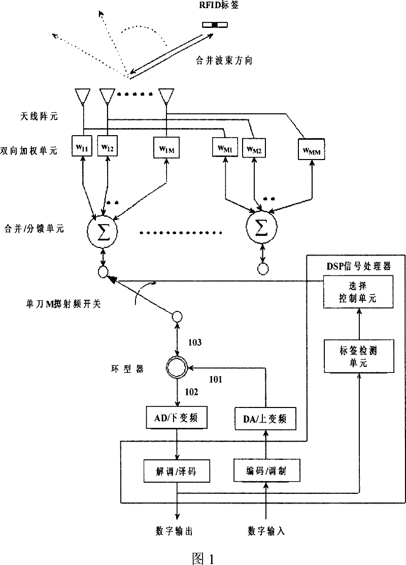
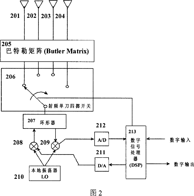
[0034] As shown in Figure 1, a RFID reader smart antenna system provided by the present invention includes an antenna array composed of multiple antenna array elements, an adjustable two-way weighting unit, a combination / distribution unit, a single-pole M-throw radio frequency switch, an A / D down-conversion unit, D / A up-conversion unit, circulator, DSP signal processor, said DSP signal processor includes demodulation / decoding unit, encoding / modulation unit, label detection unit and selection control unit, said Antenna elements are connected to an adjustable two-way weighting unit, and the adjustable two-way weighting unit is connected to a DSP signal processor through a combination / splitting unit, a single-pole M-throw radio frequency switch, a circulator, and an A / D dow...


PUM


Abstract

The invention discloses a RFID reader intelligent antenna system comprising an antenna array composed of a plurality of antenna elements, an adjustable two-way weighting unit, a merging / dividing unit, a single-pole M-throw radio frequency switch, an A / D down conversion unit, a D / A up conversion unit, a circular device and a DSP signal processor having a demodulating / decoding unit, an encoding / modulating unit, a tag detecting unit and a selection control unit. According to the invention, on one hand, the beam transmitted from the elements are merged to enhance the radio frequency energy in the determined direction or inhibit the radiation energy in other directions; on the other hand, the beam can scan in a sector zone by regulating and merging the parameters and controlling the beam direction, thereby the identification range of the reader is expanded.

Description

technical field [0001] The invention relates to an ultra-high frequency / microwave (UHF / MF) radio frequency identification (RFID) technology, in particular to an RFID reader intelligent antenna system. Background technique [0002] RFID technology is a kind of automatic identification technology. The RFID system formed by RFID technology mainly includes two parts: the reader and the tag. The reader sends a wireless signal to the tag, and the tag returns the chip data stored in it to the reader, thereby achieving the purpose of automatic identification. RFID technology can be divided into frequency bands: low frequency (125KHz), high frequency (13.56MHz), ultra-high frequency (900MHz) and microwave (2.45GHz), and can be divided into three types according to the working mode of tags: active, passive and semi-active. way. The active tag has its own power supply, and the receiving signal and the sending signal are powered by its own power supply; the pa...

Claims


Application Information

Patent Timeline
IPC IPC(8): G06K7/00H01Q21/28
Inventor 谢胜利李波邓毅华吴宗泽
Owner SOUTH CHINA UNIV OF TECH
Learn More