Method for operation of a burner in particular a burner for a gas turbine and device for carrying out said method

A technology of burner and fuel characteristics, applied in gas turbine installations, combustion methods, combustion air/fuel supply, etc., can solve problems such as increased nitrogen oxide emissions

Active Publication Date: 2007-09-19
SIEMENS ENERGY GLOBAL GMBH CO & KG
View PDF12 Cites 9 Cited by
  • Summary
  • Abstract
  • Description
  • Claims
  • Application Information

AI Technical Summary

Problems solved by technology

The problem at which the invention is based here is that changes in the fuel composition over time or fuel changes cause changes in the mixing flow field, which often lead to increased NOx emissions in the case of poor mixing

Method used


Image

  • Method for operation of a burner in particular a burner for a gas turbine and device for carrying out said method
  • Method for operation of a burner in particular a burner for a gas turbine and device for carrying out said method
  • Method for operation of a burner in particular a burner for a gas turbine and device for carrying out said method

Examples


Embodiment Construction

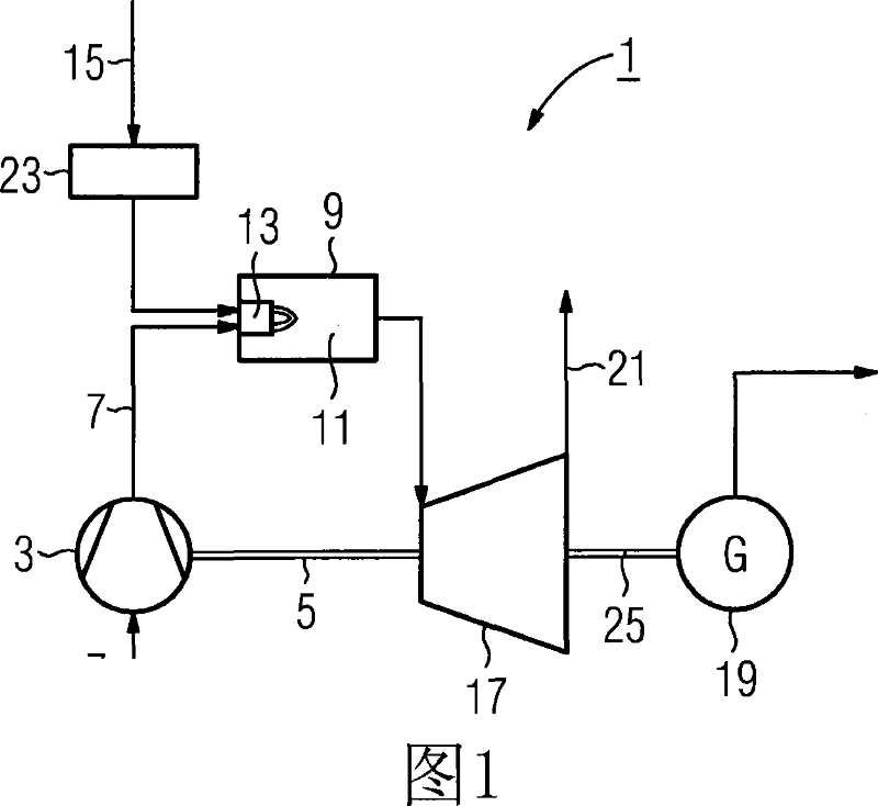
[0034] The gas turbine system shown in FIG. 1 has a gas turbine 1 with a compressor 3 , a combustion chamber 9 and a turbine 17 downstream of the combustion chamber 9 . Compressor 3 and turbine 17 are optionally coupled via a common rotor shaft 5 . A generator 19 is connected downstream of the turbine 17 and is coupled to the turbine 17 , for example via a generator shaft 25 . The combustion chamber 9 comprises a combustion zone 11 and a burner 13 protruding into the combustion zone 11 for burning a liquid or gaseous fuel 15 . When the gas turbine 1 is working, the air 7 is sucked into the compressor 3, where the air is compressed. The compressed air 7 is fed to the burner 13 as combustion air and mixed with fuel 15 . The fuel-air mixture thus formed is combusted in the combustion zone 11 , producing very hot combustion gases. The high-temperature combustion gas is delivered to the turbine 17, where it expands to perform work, thereby driving the rotor shaft 5 on the compre...


PUM


Abstract

The invention relates to a method for operation of a burner (13), whereby a fuel (15) is supplied to the burner (13), sprayed into the combustion air (7), mixed with the combustion air (7) to give a fuel / air mixture and burnt in a combustion chamber (11). With regard to a combustion particularly low in pollutants and, in order to reduce the nitrogen oxide emissions with relation to achieving a given nitrogen oxide emission level, a change in parameters characterising the fuel (15) is determined. Such a parameter may, for example, be the Wobbe index (WI). The invention further relates to a device for carrying out said method, comprising a fuel treatment device (23), with an analytical device (27) for the analysis of the current fuel composition and a monitoring and control system (29).

Description

technical field [0001] The invention relates to a method of operating a burner, wherein a fuel is delivered to said burner, injected into combustion air, mixed with said combustion air to form a fuel-air mixture, and discharged in a combustion chamber to burn. Background technique [0002] In view of international efforts to reduce pollutant emissions from heating systems (especially gas turbines), a variety of nitrogen oxides (NO X ) particularly low emission burners and their method of operation. In such cases, it is often very important that these burners do not work with only one fuel, but can use various fuels as required, such as oil, natural gas and / or synthesis gas (eg coal gas) , and even a combination of different fuels to achieve the purpose of improving supply security and flexibility during work. Such a burner is described, for example, in EP 0 276 696 B1. [0003] As a result, the problem of whether the combustion in the burner is stable will arise, and the...

Claims


Application Information

Patent Timeline
Patent Type & Authority Applications(China)
IPC IPC(8): F23R3/28F23N5/00F02C3/30
CPCF23N2041/20F23L2900/07002F23L2900/07009F02C3/20F23N2021/10F23L2900/07008F02C9/40F23L7/00F23N2221/10F23N2241/20
Inventor 伯恩德·普拉德
Owner SIEMENS ENERGY GLOBAL GMBH CO & KG
Why Eureka
Try Eureka