
Small-sized blowing fan

A blower fan, small-scale technology, applied in non-variable pumps, machines/engines, non-displacement pumps, etc., can solve the problems of reducing fan speed and pressure, blower fans cannot use motor stator coils, and space constraints. Achieve the effect of meeting the cooling needs

Inactive Publication Date: 2007-09-26
SUNONWEALTH ELECTRIC MACHINE IND
View PDF0 Cites 1 Cited by
  • Summary
  • Abstract
  • Description
  • Claims
  • Application Information

AI Technical Summary

Problems solved by technology

[0004] However, with the precision and complexity of integrated circuit layout, especially for thin and miniaturized electronic system equipment, the complex circuit design makes the temperature of the internal microchip rise sharply. Increasing the heat dissipation area, or using heat pipes to transfer heat energy, are no longer enough to solve the problem of rapid heat accumulation in today's systems; however, the above-mentioned conventional blower fans have difficulties in miniaturization and thinning, so they cannot be applied Thin electronic system equipment
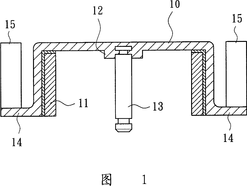
[0005] If the thickness of the above-mentioned conventional blower fan is directly reduced, the heat dissipation efficiency of the fan will be directly affected; because, once the overall thickness of the fan wheel 10 is reduced, the space available for the stator configuration inside the fan wheel 10 must be limited, and the fan wheel 10 must be limited. This blower fan cannot use a larger power motor stator coil; moreover, reducing the overall thickness of the conventional blower fan also limits the area of ​​each blade 15, which will inevitably reduce the wind speed and wind pressure of the fan.

Method used


Image

  • Small-sized blowing fan
  • Small-sized blowing fan
  • Small-sized blowing fan

Examples


Embodiment Construction

[0018] In order to have a further understanding and understanding to the purpose of the present invention, technical features and advantages thereof, the preferred embodiments are described in detail as follows:

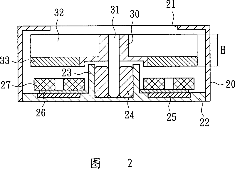
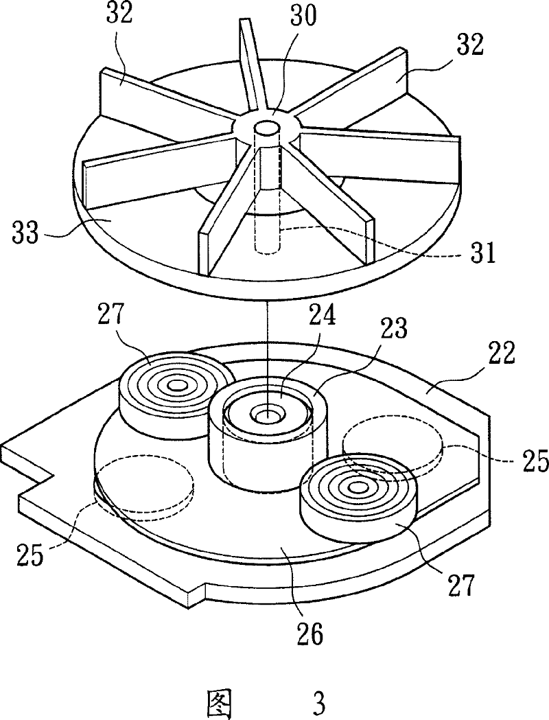
[0019] Referring to Figures 2 and 3, the first embodiment of the present invention is a small blower fan, which is mainly used for heat dissipation of microchips in thin electronic system equipment. It includes a shaft seat 30, and a rotating shaft is fixed at the center of the shaft seat 30 31. Several blades 32 and magnets 33 are fixed outwards on its outer periphery. Each blade 32 protrudes outward from the outer periphery of the shaft seat 30 and is arranged in a regular radial pattern. The magnets 33 are located in the area that each blade 32 can cover when it rotates. within the scope;

[0020] Moreover, if the overall total height of the blade 32 and the magnet 33 is H, the height of the blade 32 must account for more than 30% of the total height H, and the he...


PUM


Abstract

A small blower fan comprises a shaft base whose center fixed with a rotary shaft and whose outside fixed several vanes and magnets, with each vane arranged in regular radiation, magnets located within the boundary covered by the vanes in rotation, and the height of the vane must be over thirty percent of the total height of the magnet. It is not only small and thin, it can meet the wind blowing volume and heat radiation requirement.

Description

technical field [0001] The invention relates to a small blower fan, especially a shaft seat with a rotating shaft in the center, several blades and magnets fixed outward on the outer periphery, and the magnets are placed under each blade in the shape of a plate, which can achieve the purpose of miniaturization and thinning Small blower fan. Background technique [0002] Referring to Fig. 1, a conventional blower fan includes a fan wheel 10, a magnet 11 is fixed on the inner wall of the fan wheel 10, and a protruding shaft seat 12 is provided at the center, and a rotating shaft 13 is fixed on the shaft seat 12; [0003] In addition, the outer peripheral surface of the fan wheel 10 extends outwards with a spoke plate 14, and the spoke plate 14 is provided with several radially uniformly distributed blades 15; therefore, when the blower fan rotates, it can drive and attract the airflow above the fan wheel 10. , and blow out to the side through each blade 15, so as to provide h...

Claims


Application Information

Patent Timeline
IPC IPC(8): F04D17/08
Inventor 洪银树尹佐国
Owner SUNONWEALTH ELECTRIC MACHINE IND
Learn More