
An energy storage battery heat dissipation bracket capable of efficiently dissipating heat

A technology of energy storage battery and heat dissipation bracket, which is applied to secondary batteries, battery pack components, circuits, etc., can solve the problem of limited remaining space of containerized energy storage batteries, difficulty in parameters such as cold wind direction and wind speed, and difficulty in installing volume fans. and other problems, to achieve compact structure, improve heat dissipation effect, and ensure the effect of heat dissipation

Active Publication Date: 2022-04-22
镇江赛尔尼柯自动化股份有限公司
View PDF7 Cites 0 Cited by
  • Summary
  • Abstract
  • Description
  • Claims
  • Application Information

AI Technical Summary

Problems solved by technology

[0003] The mainstream energy storage battery cooling methods include air cooling and liquid cooling. Air cooling mainly relies on cooling fans and other air supply components. However, the remaining space inside the container-type energy storage battery is limited, and it is difficult to install a large fan. , and then can only use the air supply method of porous air duct as an alternative, but the position of the air duct is relatively fixed. Seriously affect the effect of air cooling; compared with the way of air cooling, the effect of liquid cooling will be more obvious, but when the liquid cooling system works alone, it can mainly cool down the side of the container quickly and efficiently, and the heat in the container is still Difficult to dissipate in time, the overall cooling effect is not ideal

Method used


Image

  • An energy storage battery heat dissipation bracket capable of efficiently dissipating heat
  • An energy storage battery heat dissipation bracket capable of efficiently dissipating heat
  • An energy storage battery heat dissipation bracket capable of efficiently dissipating heat

Examples


Embodiment Construction

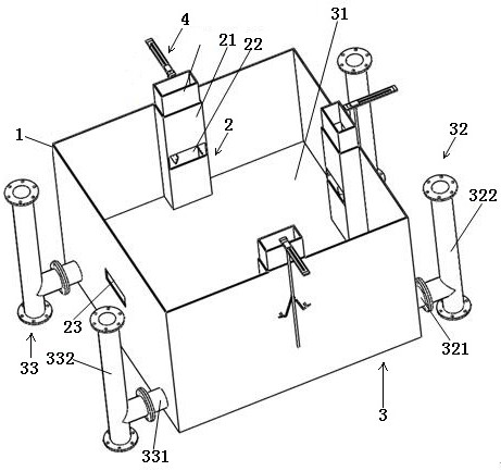
[0035] Attached below Figure 1-7 The preferred embodiments of the present invention are described in detail, so that the advantages and features of the present invention can be more easily understood by those skilled in the art, so as to define the protection scope of the present invention more clearly.

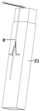
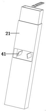
[0036] In order to improve the heat dissipation effect of the energy storage battery bracket, in order to provide technical reference for the development of the container energy storage system and market competition, this embodiment discloses an energy storage battery heat dissipation bracket that can dissipate heat efficiently, including the bracket body 1, forced ventilation Module 2, water-cooled heat dissipation chassis module 3 and flow field control device module 4, the forced ventilation module 2 includes a ventilation duct 21, an air inlet 22 and an air outlet 23, and a ventilation duct 21 is respectively provided on the inside of three sides of the bracket body 1 , ...


PUM


Abstract

The invention discloses an energy storage battery cooling bracket capable of efficiently dissipating heat, which includes a bracket body, a forced ventilation module, a water-cooled heat dissipation chassis module, and a flow field control device module. The forced ventilation module includes a ventilation duct, an air inlet and an air outlet. One of the flow field control device modules is connected in the air duct; the water cooling chassis module is arranged at the bottom of the support body. The heat dissipation bracket combines two cooling modes of air cooling and water cooling, the cooling effect is improved, and the design of the ventilation duct and the bracket body is integrated, no additional air duct is required, and the position and angle of the deflector in the ventilation duct can be adjusted Flexible adjustment under different working conditions, which meets the air volume required for cooling the energy storage battery and ensures the uniformity of air supply in the air duct under various working conditions; multi-bracket modules can be superimposed through the cooperation of the male and female ports at both ends of the ventilation duct The installation realizes the modularization of the thermal management structure, compact structure, easy disassembly and assembly and easy integration.

Description

technical field [0001] The invention relates to the technical field of energy storage battery heat dissipation, in particular to an energy storage battery heat dissipation bracket capable of efficiently dissipating heat. Background technique [0002] With the gradual improvement of the national grid construction, the demand for energy storage technology continues to increase. As a key component of energy storage equipment, the battery pack directly affects the performance of the energy storage system. Large-capacity containerized energy storage systems generally consist of tens of thousands of batteries closely arranged. The battery layout parameters have been set before leaving the factory, so it is difficult to adjust the battery layout space. When charging and discharging, the battery will generate a lot of heat, coupled with the impact of the dense space layout of the battery, even if the temperature of the total layout space in the container can be effectively reduced ...

Claims


Application Information

Patent Timeline
Patent Type & Authority Patents(China)
IPC IPC(8): H01M50/244H01M50/251H01M10/613H01M10/617H01M10/627H01M10/6554H01M10/6556H01M10/6563H01M10/6568
CPCH01M10/613H01M10/627H01M10/617H01M10/6556H01M10/6563H01M10/6554H01M10/6568H01M50/20Y02E60/10
Inventor 施红胡亮春朱信龙邹燚涛杨凯杰徐文冰陈佳敏
Owner 镇江赛尔尼柯自动化股份有限公司
Learn More