Check patentability & draft patents in minutes with Patsnap Eureka AI!

Projector system

A technology of projection optical system and image projection, which is applied in the direction of instruments, optics, color TV components, etc., can solve the problems of disturbance speckle and interference pattern, and achieve the effect of high transmission image uniformity and high visual quality

Inactive Publication Date: 2007-09-26
KONINK PHILIPS ELECTRONICS NV
View PDF0 Cites 2 Cited by
  • Summary
  • Abstract
  • Description
  • Claims
  • Application Information

AI Technical Summary

Problems solved by technology

Three examples in this list of problems are given below: i) speckle, laser light is coherent light, thus causing perturbed speckle and interference patterns; ii) large depth of focus, which makes defects optically visible in the image; iii) The question of how to miniaturize the system without sacrificing illumination light

Method used


Image

  • Projector system
  • Projector system

Examples


Embodiment Construction

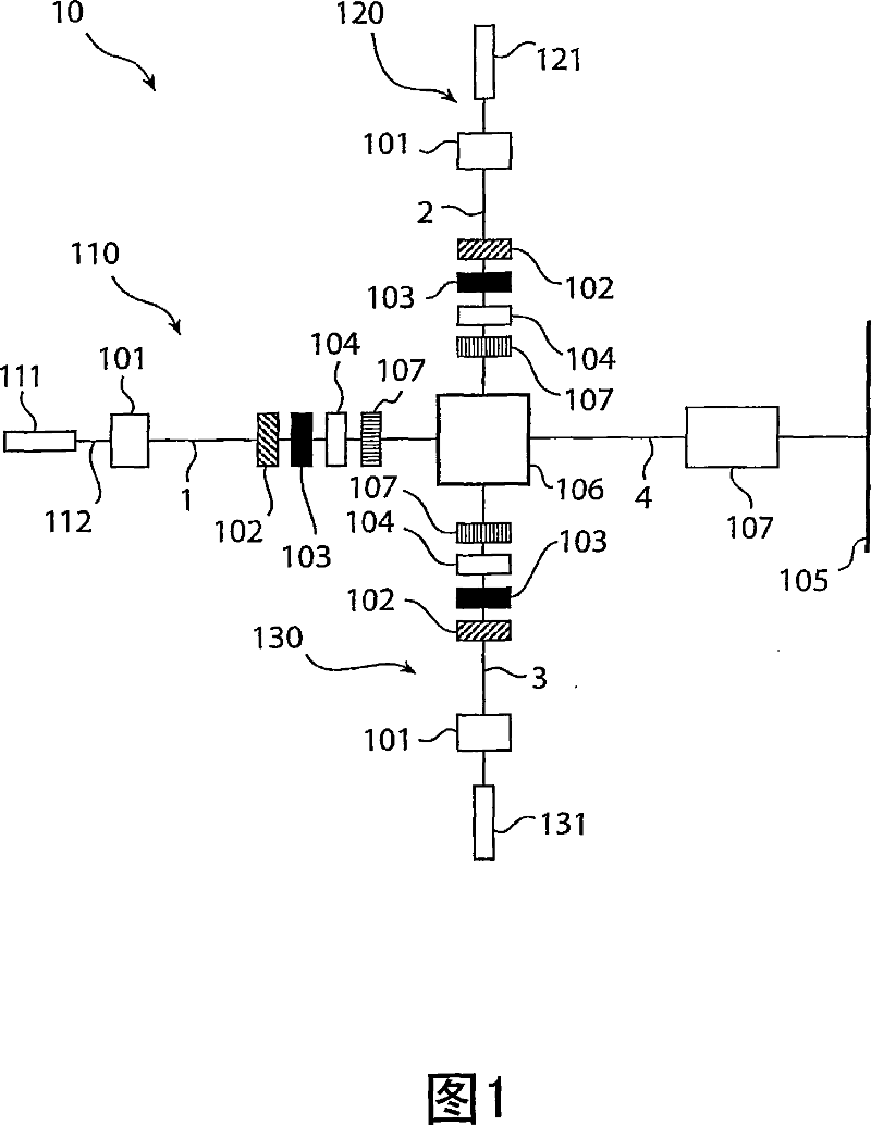
[0026] In order to provide a better understanding of the present invention, preferred embodiments according to the present invention will be described. Reading this description in conjunction with the accompanying drawings will facilitate understanding of the contents. In the drawings, like reference numerals are used to designate like or corresponding parts throughout the figures. The figures are not drawn to scale. The projector system shown in the figures suitably includes conventional electronics for operating eg the light source and image panel, which are well known in the art and will not be described in detail.

[0027] Although the invention will be described with respect to transmissive LCD projector systems, it should be understood that the invention is also applicable to other types of light modulating projectors, for example, projectors including reflective liquid crystal silicon (LCOS) display panels.

[0028] Fig. 1 is a schematic diagram of an image projection...


PUM


Abstract

The present invention provides an laser based image projection system for displaying images, which comprises an LCD device and projection optics. By introducing a diffuser between the LCD device and the projection optics, the quality of the projected image is improved. The visibility of material imperfections in the optical the beam path, which were previously visible in the projected image due to the large field-of-depth of the system, is now reduced.

Description

technical field [0001] The present invention relates generally to image projection systems for displaying images, and more particularly to image projection systems including laser-based illumination sources. Background technique [0002] The projector can be used both in rear image projection systems and in front image projection systems. In a rear projection system, a projector projects an image representing television or data graphic information on the back of a transparent diffuser screen, the front of which faces the viewer. In a front projection system, a projector projects an image representing television or data graphic information on the front of a reflective screen facing the viewer. [0003] To meet the commercial demand for projectors, there is a constant quest to produce systems that are smaller, last longer, and project brighter images with higher contrast. [0004] A schematic description of a conventional front LCD projector using a lamp as an illumination s...

Claims


Application Information

Patent Timeline
Patent Type & Authority Applications(China)
IPC IPC(8): G02F1/1335
CPCH04N9/3161H04N9/3197H04N9/3105G02B27/48H04N9/315
Inventor 安德里阿努斯·J.·S.·M.·德瓦恩霍尔格·门希格罗·霍伊斯勒埃德·范登布兰特
Owner KONINK PHILIPS ELECTRONICS NV
Features
  • R&D
  • Intellectual Property
  • Life Sciences
  • Materials
  • Tech Scout
  • Unparalleled Data Quality
  • Higher Quality Content
  • 60% Fewer Hallucinations
Learn More