Medical electric drill

An electric drill and drill bit technology, which is applied in the field of medical equipment, can solve the problems of small output torque of planetary gears, high price, and difficulty in processing and assembling planetary gears, and achieve increased output torque, low production cost, and high transmission efficiency. high effect

Inactive Publication Date: 2007-10-03
苏州华盛医疗器械有限公司
View PDF0 Cites 8 Cited by
  • Summary
  • Abstract
  • Description
  • Claims
  • Application Information

AI Technical Summary

Problems solved by technology

[0002] The medical electric drill in the prior art usually includes a housing, a drill bit holder pivotally connected to the housing, a motor connected to the drill bit holder through a transmission device, and a control switch, wherein the transmission device usu

Method used


Image

  • Medical electric drill

Examples


Embodiment Construction

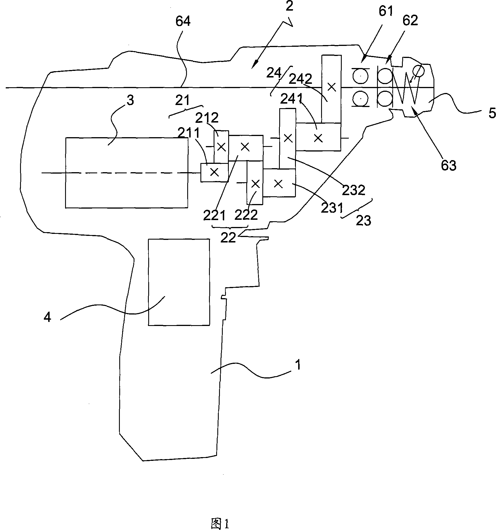
[0012] Referring to Figure 1, a medical electric drill includes a housing 1, a drill holder 5 pivotally connected to the housing 1, and a motor that is connected to the drill holder 5 through a transmission device 2. 3. Control switch 4. Orthopedic surgery cutters or drill bits can be clamped as required on the drill bit holder 5 .

[0013] The transmission device 2 includes N stages of gear reduction mechanisms in transmission connection with each other, where N is a natural number greater than or equal to 1. Usually, the value of N varies flexibly according to the reduction ratio of the medical electric drill, the modulus of the reduction gear, and the gears. Generally, N is a natural number greater than or equal to 2 and less than or equal to 6; in a preferred embodiment of the present invention, N is 4 , That is, the transmission device 2 has a four-stage reduction gear mechanism.

[0014] Each stage of the gear reduction mechanism is composed of a pinion gear and a bull...


PUM


Abstract

A medical electric drill with slow rotation speed is composed of a shell, a drill bit holder, a drive unit and an electric motor for driving said drill bit holder via said drive unit. Said drive unit is an N-stage gear-type speed reducer, which features hat the mutually engaged big and small gears in each stage are coaxial.

Description

technical field [0001] The invention belongs to the field of medical instruments, in particular to a medical slow drill. Background technique [0002] The medical electric drill in the prior art usually includes a housing, a drill bit holder pivotally connected to the housing, a motor connected to the drill bit holder through a transmission device, and a control switch, wherein the transmission device usually Planetary gear trains are used for reduction transmission, because the processing and assembly of planetary gears are very difficult, so they are usually expensive; in addition, the output torque of planetary gears is small, and the energy loss is serious. Contents of the invention [0003] The purpose of the present invention is to provide a medical electric drill with high transmission efficiency and low cost. [0004] The technical solution adopted in the present invention is: a medical electric drill, comprisi...

Claims


Application Information

Patent Timeline
IPC IPC(8): A61B17/16A61B17/32A61B17/00
Inventor 任朴鲁仁义
Owner 苏州华盛医疗器械有限公司
Why Eureka
Try Eureka