Firing machine type thermal decomposition furnace

A thermal decomposition furnace and thermal decomposition technology, used in lighting and heating equipment, incinerators, combustion types, etc., can solve the problems of increased equipment costs, insufficient combustion air for cooling, uneconomical, etc., and achieve the effect of improving the carbonization rate.

Inactive Publication Date: 2007-10-03
高桥 贤三
View PDF0 Cites 7 Cited by
  • Summary
  • Abstract
  • Description
  • Claims
  • Application Information

AI Technical Summary

Problems solved by technology

[0004] However, the problem with the gasification and melting device of Patent Document 1 is that combustion air is blown in from the grate to partially burn while cooling the grate, and gasification by thermal decomposition proceeds at the same time, so most of the generated gas is The CO obtained from incomplete combustion, the flammable gas produced by the thermal decomposition of garbage is less, and the amount of combustion air flowing through is not enough to cool the grate
In addition, the conventional continuous carbonization furnace requires a secondary furnace because the pyrolysis gas is processed outside the furnace, and there is a problem that the equipment cost increases, and the thermal decomposition heat needs to be supplied from the outside, such as a combustion furnace, so it is not economical.

Method used


Image

  • Firing machine type thermal decomposition furnace
  • Firing machine type thermal decomposition furnace
  • Firing machine type thermal decomposition furnace

Examples


Embodiment Construction

[0026] Embodiments of the present invention will be described below with reference to the accompanying drawings.

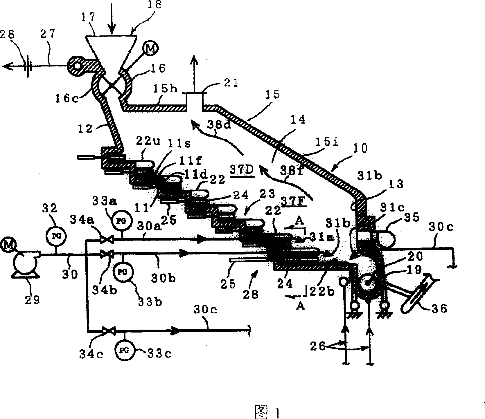
[0027] In Fig. 1, 10 is a furnace body formed of refractory material, and a bottom 11 is formed in a step shape, an upper wall 12 is set on the upper section side of the bottom 11, a lower wall 13 is set on the lower section side of the bottom 11, and a bottom wall 13 is set on both sides of the bottom 11. In the side wall 14, the ceiling wall 15 is formed by the inclined wall part 15i and the horizontal wall part 15h from the lower part wall 13 to the upper part wall 12.

[0028] On the ceiling wall 15 on the side of the upper wall 12, a garbage input device 18 composed of a rotary feeder 16 having a casing made of a refractory material and a hopper 17 provided on the rotary feeder 16 is provided. If this garbage input device 18 can drop garbage into the furnace body 10 that does not use the rotary feeder 16 in an airtight state, it can also be configured as, for...


PUM


Abstract

The present invention provides one kind of stocker type thermal decomposing furnace to decompose garbage to generate fuel gas. The thermal decomposing furnace has a stepped grate combination, a stocker to extrude garbage downwards, a garbage feeder over the stepped grate combination, a fuel gas supply device below the stepped grate combination. The present invention can convert most of the garbage into fuel gas and decompose garbage with the combustion heat in raised carbonization rate.

Description

technical field [0001] The present invention relates to a coal stoker thermal decomposition system capable of generating combustion gas from the combustible garbage when incinerating combustible garbage such as industrial waste composed of municipal garbage, wood chips, and waste plastics, and using the combustion gas as a heat source. furnace. Background technique [0002] The stoker furnace is composed of stepped and inclined grate groups, and a pusher for making the incineration flow down is arranged on each section of the grate, so that the incineration put in from the upper part is combusted, and squeezed by a suitable pusher at the same time. The incinerated material is pressed to flow to the lower stage and incinerated. Because the width of the grate can be freely changed to match the processing capacity of the incinerated material, it is widely used in the incineration of municipal waste. In this stoker furnace, combustion air is supplied from the grate to combust t...

Claims


Application Information

Patent Timeline
Patent Type & Authority Applications(China)
IPC IPC(8): F23G5/027
Inventor 高桥贤三
Owner 高桥 贤三
Why Eureka
Try Eureka