Pulse width modulation circuit

A technology of pulse width modulation and pulse width, applied in the direction of pulse duration/width modulation, etc., can solve the problems of signal waveform jitter, increase circuit scale and cost, and affect equipment operation

Inactive Publication Date: 2007-10-03
CYPRESS SEMICON CORP
View PDF0 Cites 11 Cited by
  • Summary
  • Abstract
  • Description
  • Claims
  • Application Information

AI Technical Summary

Problems solved by technology

However, jitter occurs in the signal waveform of the PWM output because its high level period contains both increased periods and non-increased periods
Due to the jitter in the PWM output signal waveform, the signal to the engine load or lighting equipment will include distortion components in it, which will affect the operation of the equipment
[0006] A possible solution to eliminate this distortion is to use a filter etc., but this also involves the problem of increasing the circuit scale and cost

Method used


Image

  • Pulse width modulation circuit
  • Pulse width modulation circuit
  • Pulse width modulation circuit

Examples


no. 1 example

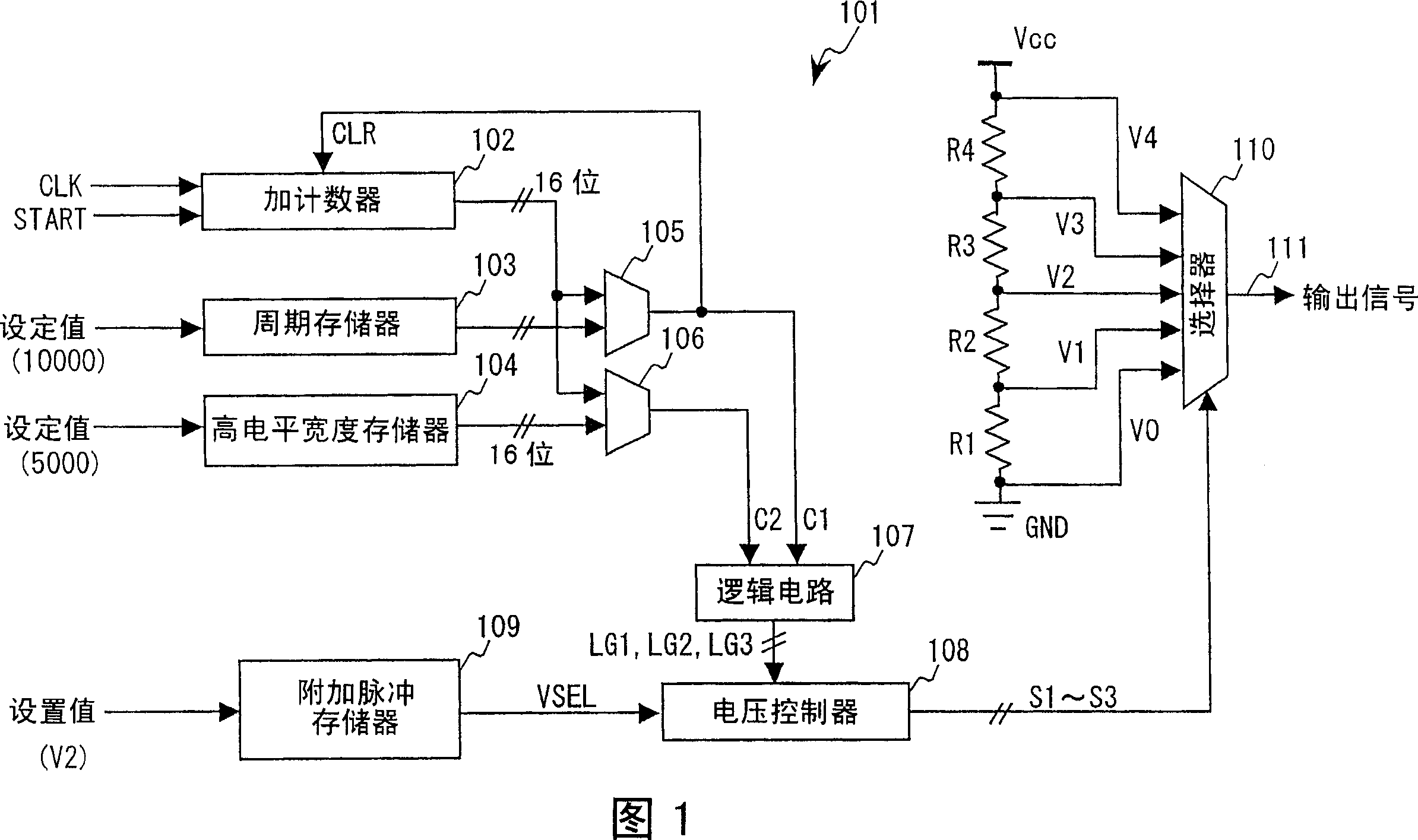
[0032] FIG. 1 is a block diagram of a PWM circuit implemented by a multi-rate method according to a first embodiment of the present invention. Multi-rate PWM circuit 101 includes up counter 102, period value register 103, high level width register 104, comparators 105 and 106, logic circuit 107, voltage controller 108, additional pulse register 109, selector 110, and constitute voltage divider Resistors R1, R2, R3 and R4 of the resistor circuit. Assume that the reference clock CLK, the start signal START, and the setting values ​​are supplied from outside such as an oscillator and the CPU.

[0033] When the start signal START is input, the up counter 102 increases synchronously with each reference clock CLK to output a 16-bit count value. The count value is set to 0 (zero) in the initial state of the up counter 102 , and is reset to 0 (zero) when the clear CLR signal is input from the comparator 105 .

[0034] For example, the period value register 103 registers therein 1000...

no. 2 example

[0052] Next, a PWM circuit implemented by a multi-rate method according to a second embodiment of the present invention is shown in FIG. 6 . The same elements as those of the first embodiment in FIG. 1 are designated with the same reference numerals. The multi-rate PWM circuit 201 differs from the first embodiment in that the multi-rate PWM circuit 201 further includes an additional pulse width register 202 and a comparator 203 , and also includes a logic circuit 204 instead of the logic circuit 107 .

[0053] For example, the additional pulse width register 202 registers therein 5002 as a set value in advance, and it continuously outputs the 16-bit set value ( 5002 ) to the comparator 203 . The comparator 203 judges whether the 16-bit count value output by the up counter 102 reaches the set value (5002) registered in the additional pulse width register 202, and when the count value reaches 5002, the comparator 203 output has a width equivalent to one reference clock. signal ...

no. 3 example

[0061] Next, a PWM circuit implemented by a multi-rate method according to a third embodiment of the present invention is shown in FIG. 8 . The same elements as in FIGS. 1 and 6 are designated with the same reference numerals. The difference between the multi-rate PWM circuit 301 and the second embodiment lies in the logic circuit 302 , the voltage controller 303 , and the additional pulse register 304 .

[0062] In the logic circuit 302, although the same signals C1 to C3 as in the second embodiment are input thereto, the signals generated thereby are four signals LG1, LG2, LG3, LG4. In addition, the operation of the output signals LG1 and LG2 is the same as that of the signals in FIG. 7 . For the signal LG3, the same signal as the signal C2 is output. A signal LG4 having a width of the interval from the falling edge of the signal C2 of the width t2 to the rising edge of the signal C3 of the width t21 is generated. The circuit for generating signal LG4 can be realized by u...


PUM


Abstract

A PWM circuit includes a counter, a cycle register, a cycle detector, a pulse width register, a pulse width detector, an additional pulse width register, a voltage generator, a selector, and a voltage controller. The voltage controller controls the selector so as to add a first additional pulse at a first voltage to the end of a pulse width, based on a cycle detection signal outputted by the cycle detector, a pulse width detection signal outputted by the pulse width detector, and a set value indicating the first voltage of the first additional pulse outputted by the additional pulse register, thereby deciding a voltage outputted from the PWM circuit and a period in which the voltage is output.

Description

technical field [0001] The present invention relates to a pulse width modulation (PWM) circuit according to a multi-rate method. Background technique [0002] Conventionally, a PWM circuit that controls the supply of electric power to a load by changing the duty ratio of a pulse signal has been used to control the speed of a motor, dim a lighting device, and the like. When the high-level period of such a PWM circuit is extended, the electric power supplied to the engine and the lighting equipment increases, and as a result, the rotational speed of the engine and the brightness of the lighting equipment increase. Conversely, when the high level period thereof is shortened, the electric power supplied to the engine and the lighting equipment is reduced, resulting in a decrease in the rotational speed of the engine and the brightness of the lighting equipment (see, for example, Japanese Unexamined Patent Application Publication No. 07-183779). [0003] Usually, the change of t...

Claims


Application Information

Patent Timeline
Patent Type & Authority Applications(China)
IPC IPC(8): H03K7/08
CPCH03K7/08
Inventor 松井聪
Owner CYPRESS SEMICON CORP
Why Eureka
Try Eureka