Anti chokage water inflow distributor for manmade marsh

A technology of constructed wetlands and distributors, applied in chemical instruments and methods, biological water/sewage treatment, water/sludge/sewage treatment, etc., can solve the problems of blockage and uneven distribution, prolong the operating life and reduce the construction work. The effect of simple operation and maintenance

Active Publication Date: 2007-10-10
江苏东大科技园发展有限公司
0 Cites 16 Cited by

AI-Extracted Technical Summary

Problems solved by technology

[0005] Technical problem: The present invention provides an anti-clogging water inlet distribution device for subsurface flow constr...

Method used

The anti-impact baffle plate is arranged along the width direction of the water-collecting sedimentation tank, 0.90m high, and the top is flush with the water-collecting sedimentation tank, which can prevent short flow and intercept part of the floating matter in the sewage, and play a diversion effect simultaneously.
[0027] The perforated pipe is arranged at the front end of the water inlet distributor, and the length is determined along the width o...

Abstract

This invention relates to an anti-blockage inlet water distributor for artificial wetland, which comprises a punched pipe, an anti-shock baffle, a precipitation tank, a grid, a gravel area, and a porous water-distribution perforated wall. The punched pipe is set at the upper part of the water inlet face of the precipitation tank. The anti-shock baffle is in the precipitation tank facing the inlet of the punched pipe. The grid is set at the upper part of the water outlet face of the precipitation tank, and through connected with the water inlet face of the gravel area beside the precipitation tank. The porous water-distribution perforated wall is set at the water outlet face of the gravel area. The water outlet face of the inlet water distributor is set at the outer surface of the porous water-distribution perforated wall. The inlet water distributor can ensure uniform water distribution in all width and depth of the artificial wetland, and ensure normal working of the artificial wetland system.

Application Domain

Technology Topic

MarshEngineering +3

Image

  • Anti chokage water inflow distributor for manmade marsh
  • Anti chokage water inflow distributor for manmade marsh
  • Anti chokage water inflow distributor for manmade marsh

Examples

  • Experimental program(1)

Example Embodiment

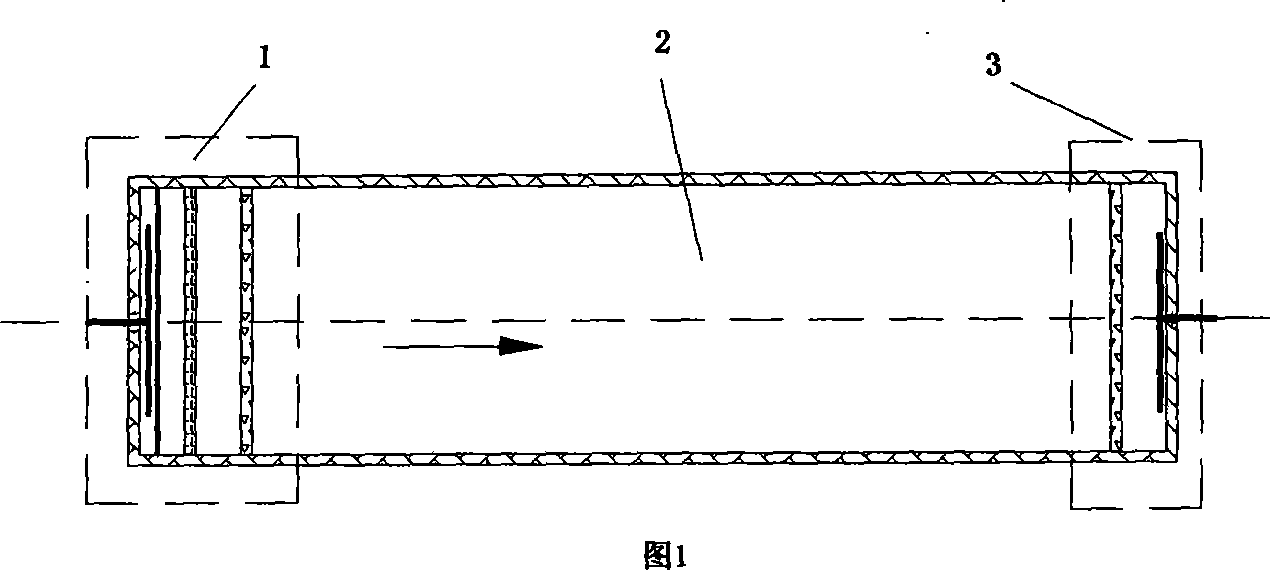
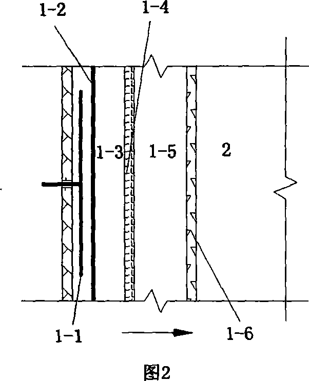
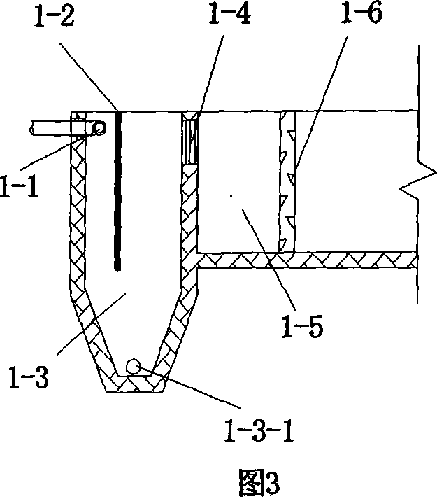
[0025] The invention is an anti-clogging artificial wetland water inlet distributor, which includes six parts: a perforated pipe, an anti-impact baffle, a water-collecting sedimentation tank, a grid, a gravel area, and a porous sprinkling wall.
[0026] Among them, a perforated pipe 1-1 is provided on the upper part of the water inlet surface of the water collection sedimentation tank 1-3, and an anti-impact baffle 1-2 is provided in the water collection sedimentation tank 1-3 facing the entrance of the perforated pipe 1-1. , On the other side of the catchment sedimentation tank 1-3, that is, on the upper part of the water outlet, a grid 1-4 is provided and connected with the inlet surface of the gravel area 1-5 next to the catchment sedimentation tank 1-3, and the gravel area 1- The water outlet surface of 5 is provided with a porous sprinkler wall 1-6, and the outside of the porous sprinkler wall 1-6 is the water outlet surface of the distributor. The upper and lower sides of the outer surface of the perforated pipe 1-1 are staggered with through holes.
[0027] The perforated pipe is arranged at the front end of the water inlet distributor, and the length is determined along the width of the water inlet distributor, so that the incoming flow is evenly distributed along the width direction and local impact is reduced. The diameter of the perforated pipe is 20-100mm according to the flow rate, and it is made of PVC material with evenly punched holes on it. The hole diameter is 5-15mm and the punching rate is 50%. The two ends of the perforated pipe are closed, and the middle part is connected with the water inlet valve by a tee.
[0028] The anti-impact baffle is set along the width of the water collection sedimentation tank, 0.90m high, and the top is flush with the water collection sedimentation tank, which can prevent short flow and intercept some floating substances in the sewage, and at the same time play a role of diversion.
[0029] The water collection and sedimentation tank is set in the front of the wetland and is set according to the width of the wetland. According to the calculation of the maximum design flow velocity of the vertical flow grit chamber and the maximum cross-sectional flow velocity of the wetland, the width of the catchment sedimentation tank is 0.4-0.5m. The total height of the water collection sedimentation tank is 1.5m, of which the effective water depth of the sedimentation zone 1-3-1 is 1.0-1.1m, and the sludge zone 1-3-2 is 0.4-0.5m deep. The inclination angle on both sides of the sludge bucket in the sludge area is 60°, and the bottom is provided with a sludge pipe along the width direction, and the sludge is regularly pumped out.
[0030] The grille is arranged at the water outlet of the water collection sedimentation tank and arranged along the width direction of the wetland. Considering the super height of the catchment sedimentation tank, the top of the grid is located about 0.10m below the top of the catchment sedimentation tank to ensure that the water from the catchment sedimentation tank overflows into the wetland at a certain level. It is recommended that the height of the grid is 0.25m, the net width of the grid is 10mm, and it is made of PVC or steel bars.
[0031] Sewage enters the gravel area 1-5 at the front of the wetland from the catchment sedimentation tank through the grid. The length of the gravel area is 0.5m, the area is evenly packed with gravel, and the gravel size is 30-40mm.
[0032] The perforated splash wall is built after the wetland's gravel area and is set according to the width of the wetland. The porous cloth splash wall is made of 100mm thick PVC board or 80~120mm thick concrete board. The porosity of the porous splash wall is not less than 50% to ensure the water catchment rate and reduce the resistance loss along the way.

PUM

no PUM

Description & Claims & Application Information

We can also present the details of the Description, Claims and Application information to help users get a comprehensive understanding of the technical details of the patent, such as background art, summary of invention, brief description of drawings, description of embodiments, and other original content. On the other hand, users can also determine the specific scope of protection of the technology through the list of claims; as well as understand the changes in the life cycle of the technology with the presentation of the patent timeline. Login to view more.

Similar technology patents

Oil distributor limiting structure, propeller hydraulic system and ship

ActiveCN110844031AShorten the installation and commissioning cycleIncreased operating lifePropulsive elementsPropellerHydraulic pressure
Owner:GUANGZHOU WENCHONG SHIPYARD CO LTD

Capacity control method for distribution transformer

Owner:ZAOZHUANG POWER SUPPLY COMPANY OF STATE GRID SHANDONG ELECTRIC POWER +1

Classification and recommendation of technical efficacy words

  • Increased operating life
  • Simple operation and maintenance

Seal Arrangement for a Rotating Ship Propeller Shaft

InactiveUS20140048461A1Increased operating lifeRobust and highly effective and functional arrangementEngine sealsMachines/enginesPropellerFuel tank
Owner:BLOHM VOSS IND
Why Eureka
Try Eureka