High energy vacuum CROWBAR switch based on high permitivity planar flashover

A technology of surface flashover and vacuum, applied in the field of CROWBAR switch, to achieve the effect of long service life, small working voltage and strong charge release ability

Inactive Publication Date: 2007-10-10
XI AN JIAOTONG UNIV
View PDF0 Cites 33 Cited by
  • Summary
  • Abstract
  • Description
  • Claims
  • Application Information

AI Technical Summary

Problems solved by technology

However, the currently used CROWBAR discharge switch is dif

Method used


Image

  • High energy vacuum CROWBAR switch based on high permitivity planar flashover
  • High energy vacuum CROWBAR switch based on high permitivity planar flashover
  • High energy vacuum CROWBAR switch based on high permitivity planar flashover

Examples


Embodiment Construction

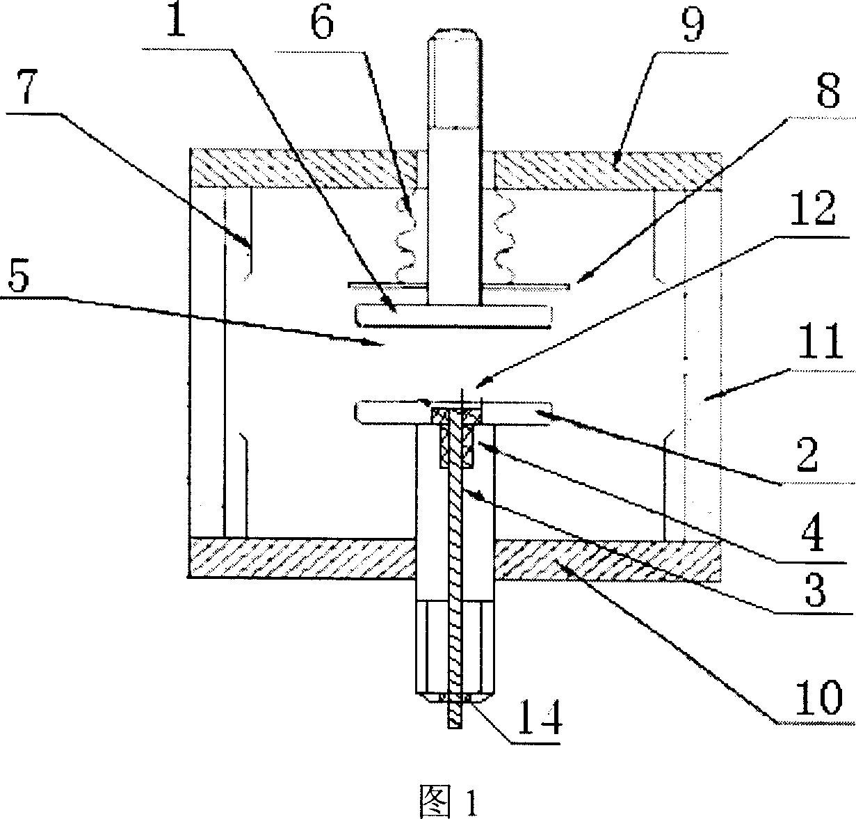
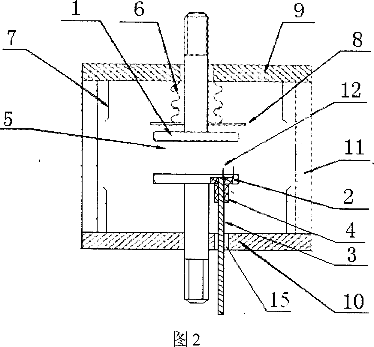
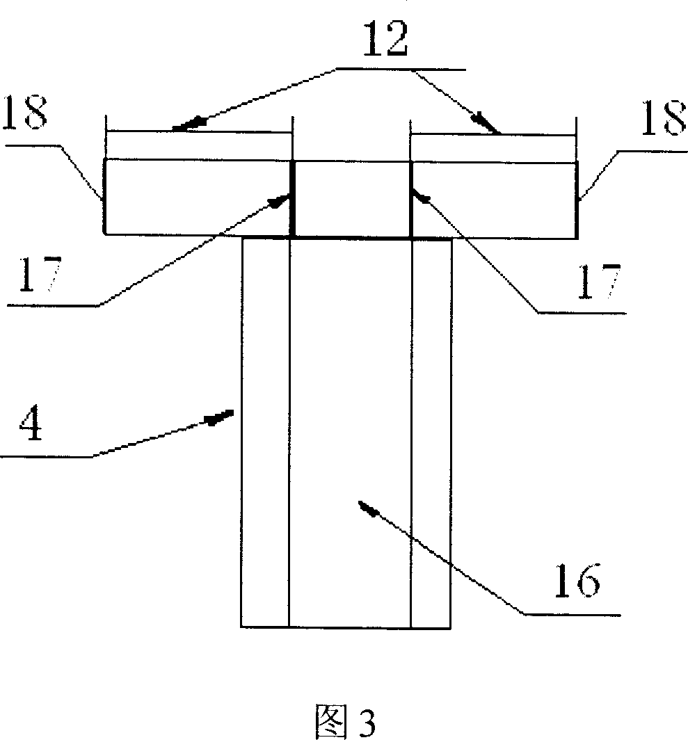
[0014] The structural principle and working principle of the present invention will be further described in detail below in conjunction with the accompanying drawings.

[0015] Referring to Fig. 1, embodiment 1, present embodiment comprises insulating casing 11 and upper electrode 1, lower electrode 2 that are arranged in insulating casing 11, form main discharge gap 5 between upper electrode 1 and lower electrode 2, upper electrode 1 and The lower electrode 2 is arranged in the insulating casing 11 through the end flange 9 and the end flange 10, and the pressure in the airtight casing formed by the insulating casing 11 and the end flanges 9, 10 arranged at both ends of the insulating casing 11 is 10 -2 ~10 -5 Pa, the upper electrode 1 is a movable electrode, and the lower electrode 2 is a fixed electrode. In the lower electrode 2, there is a creeping flashover dielectric material 4 embedded with a columnar trigger electrode 3. Between the columnar trigger electrode 3 and the ...


PUM


Abstract

The CROWBAR switch includes the insulation shell body as well as up electrode and low electrode inside the shell body. The up and low electrodes constitute main discharging gap. Pressure inside the airtight shell is 10-2 -- 10-5 Pa. At least one of up and low electrodes is movable electrode. Dielectric material flashing over along surface with trigger electrode being inlaid is setup inside the fixed electrode, or movable electrode, or fixed on one side of the fixed electrode. Discharging gap along surface is constituted between the trigger electrode and the said dielectric material. When the trigger electrode is inlaid on one side of the fixed electrode, insulating material insulates between the trigger electrode and end flange. In vacuum condition and action of trigger pulse, the invention possesses strong capability of releasing charges, very wide voltage working range, high withstanding voltage, very small working voltage, and larger discharge capacity.

Description

technical field [0001] The invention relates to a CROWBAR switch in the technical fields of pulse power technology, nuclear fusion technology and high-energy laser, and in particular to a high-energy vacuum CROWBAR switch based on high-intermediate surface flashover. Background technique [0002] The high-energy pulse discharge switch is one of the key devices commonly used in pulse power technology, nuclear fusion and high-energy laser technology. The domestic discharge switch used in pulse power technology generally has a charge transfer of about 0.2 coulombs. In foreign pulse power technology research, The single charge transfer of the discharge switch has reached 1 coulomb. With the development of strong electromagnetic pulse technology such as pulse power technology, high-energy pulse generators will play an increasingly important role, and the amount of charge transfer and pulse energy that pass through the discharge switch in a single pass are also gradually increasin...

Claims


Application Information

Patent Timeline
IPC IPC(8): H01H33/662H01H33/664H01B17/42H01H83/10
Inventor 姚学玲陈景亮孙伟
Owner XI AN JIAOTONG UNIV
Why Eureka
Try Eureka