Over-temperature protection method for transformer in reverse exciting topological power and its application circuit

A flyback topology, over-temperature protection technology, applied in emergency protection circuit devices, automatic disconnection emergency protection devices, circuit devices, etc. and other problems, to achieve the effect of no thermal shock, fast protection, and improved accuracy

Inactive Publication Date: 2007-10-10
ASTEC POWER SUPPLY (SHENZHEN) CO LTD
View PDF0 Cites 11 Cited by
  • Summary
  • Abstract
  • Description
  • Claims
  • Application Information

AI Technical Summary

Problems solved by technology

Due to the large number of components in this protection method, the large thermal shock to the power supply, the high cost (there are many corresponding components), the reliabil

Method used


Image

  • Over-temperature protection method for transformer in reverse exciting topological power and its application circuit
  • Over-temperature protection method for transformer in reverse exciting topological power and its application circuit
  • Over-temperature protection method for transformer in reverse exciting topological power and its application circuit

Examples


Embodiment 1

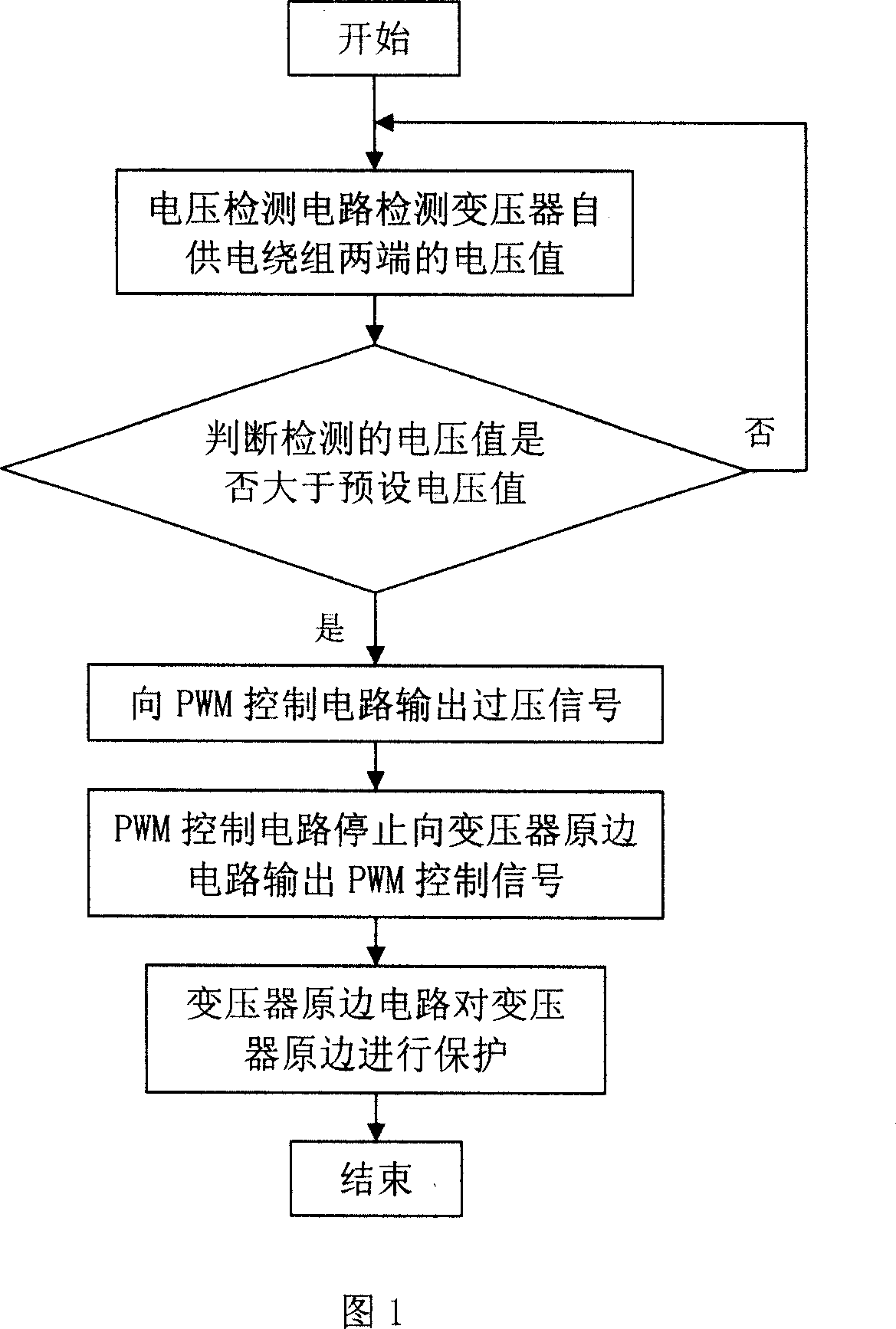
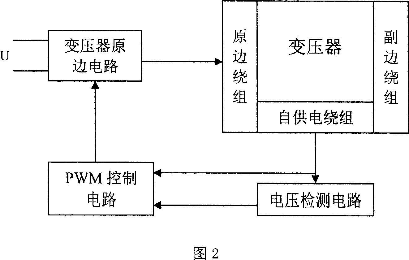
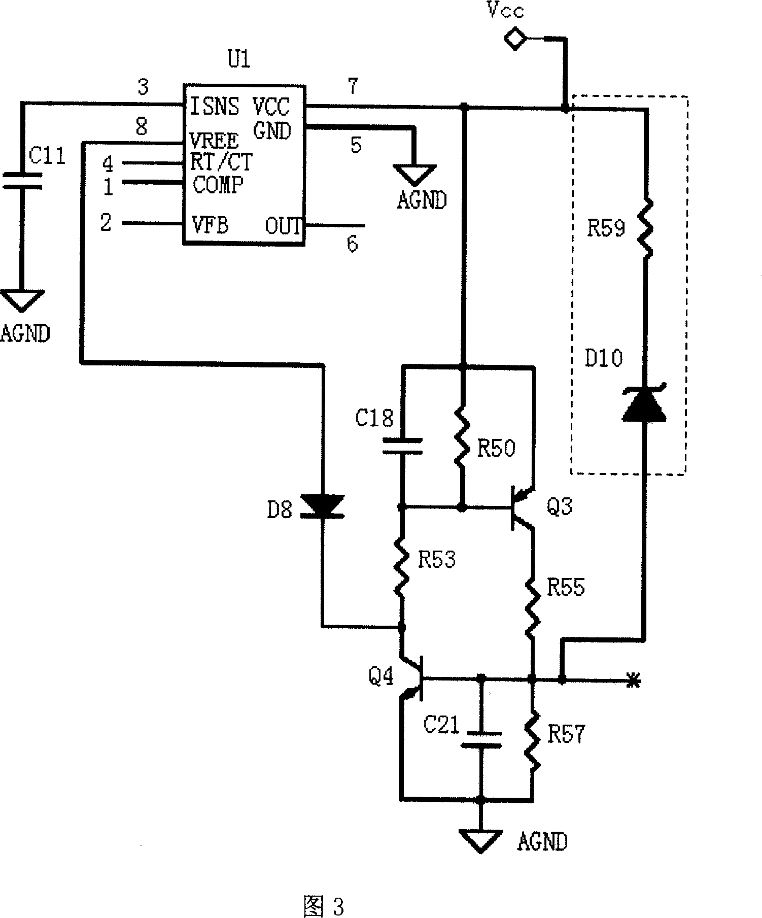
[0037] Fig. 3 is a schematic diagram of a PWM control circuit and a voltage detection circuit in Embodiment 1 of the present invention, wherein,

[0038] The voltage detection circuit includes a resistor R59 and a voltage regulator tube D10. In the frame line in the figure, one end of the resistor R59 is electrically connected to the self-powered winding of the transformer, and this end is used as the input end of the voltage detection circuit. The voltage detection circuit passes the The terminal detects the voltage at both ends of the self-powered winding of the transformer, and the other end of the resistor R59 is connected to the cathode of the voltage regulator D10, and the anode of the voltage regulator D10 is electrically connected to the PWM control circuit, and the anode of the voltage regulator D10 is used as the voltage At the overvoltage signal output end of the detection circuit, the resistor R59 is mainly used to suppress the leakage current of the regulator tube ...

Embodiment 2

[0044] Fig. 4 is a schematic diagram of the voltage detection circuit in this embodiment of the present invention. Compared with Embodiment 1, only the change in the voltage detection circuit is made. The voltage detection circuit mainly includes an operational amplifier U3, a regulator tube D11 and a resistor R54. The cathode of the voltage stabilizing tube D11 is electrically connected to the self-power supply winding of the transformer, and its anode is grounded through the resistor R54, and the anode of the voltage stabilizing tube D11 is connected to the first input terminal of the operational amplifier U3. The second input terminal of the amplifier U3 is connected to the reference power supply, and the output terminal of the operational amplifier U3 is electrically connected to the PWM control circuit; wherein, the first and second input terminals of the operational amplifier U3 are positive and negative input terminals respectively, or The reference power supply includes...


PUM


Abstract

The method includes steps: voltage-testing circuit (VTC) detects voltage value at two ends of self-powered winding of transformer; VTC determines detected voltage value and prearranged voltage value; if detected voltage value is larger than prearranged voltage value, VTC outputs voltage signal to PWM control circuit; after receiving signal of over voltage, PWM control circuit stops outputting PWM control signal to primary side of transformer; thus, primary side of transformer protects primary side and secondary side. The circuit includes primary side circuit of transformer, transformer composed of primary and secondary windings and self-powered winding, PWM control circuit, and voltage detection circuit. The invention raises reliability of over temperature protection for transformer.

Description

[technical field] [0001] The invention relates to the protection technical field of a flyback topology power supply, in particular to an overtemperature protection method for a transformer in a flyback topology power supply and an application circuit thereof. [Background technique] [0002] In the flyback topology power supply, the existing safety over-temperature protection circuit mainly judges whether the temperature is too high by detecting the transformer, power device, radiator, etc. If it is too high, protective measures are taken to protect the circuit. For example: when doing UL, TUV and other safety certification, all windings and rectifier diodes on the secondary side of the transformer will be short-circuit tested. At this time, the temperature of the tested transformer cannot exceed the design safety level. If it exceeds, it will be judged as unqualified. In the prior art, a common practice is to add a temperature probe to measure the temperature of a transforme...

Claims


Application Information

Patent Timeline
IPC IPC(8): H02H7/04H02H5/04
Inventor 张涛杨光成
Owner ASTEC POWER SUPPLY (SHENZHEN) CO LTD
Why Eureka
Try Eureka