
Secondary utilization process and device for water power residual energy

A process and residual energy technology, applied in the direction of engine components, machines/engines, mechanical equipment, etc., can solve problems such as water waste, achieve the effect of increasing power generation and avoiding harm

Inactive Publication Date: 2007-10-17
常立
View PDF0 Cites 2 Cited by
  • Summary
  • Abstract
  • Description
  • Claims
  • Application Information

AI Technical Summary

Problems solved by technology

This results in waste of water energy flowing through the turbine

Method used


Image

  • Secondary utilization process and device for water power residual energy
  • Secondary utilization process and device for water power residual energy
  • Secondary utilization process and device for water power residual energy

Examples


Embodiment Construction

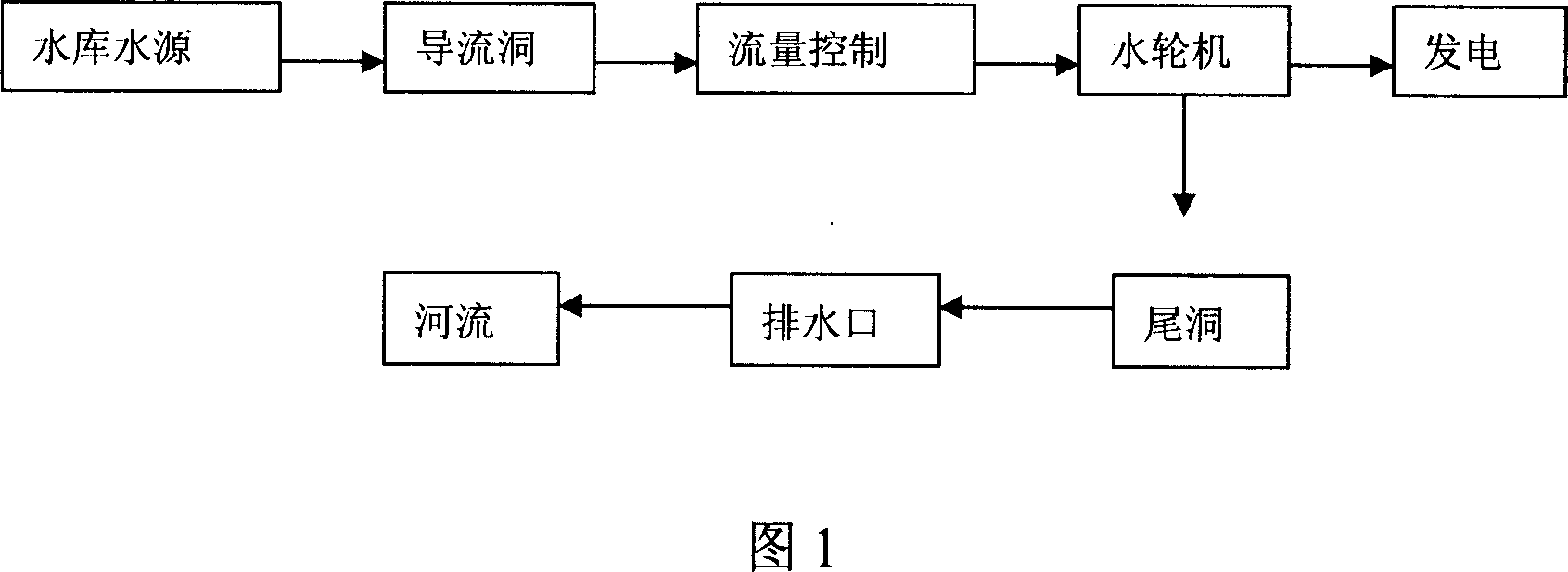
[0014] Figure 1 is a flow chart of the existing water energy utilization process. The water source enters the water turbine to generate electricity through the flow control of the diversion tunnel, then enters the tail hole, and then discharges into the river through the tail hole outlet.

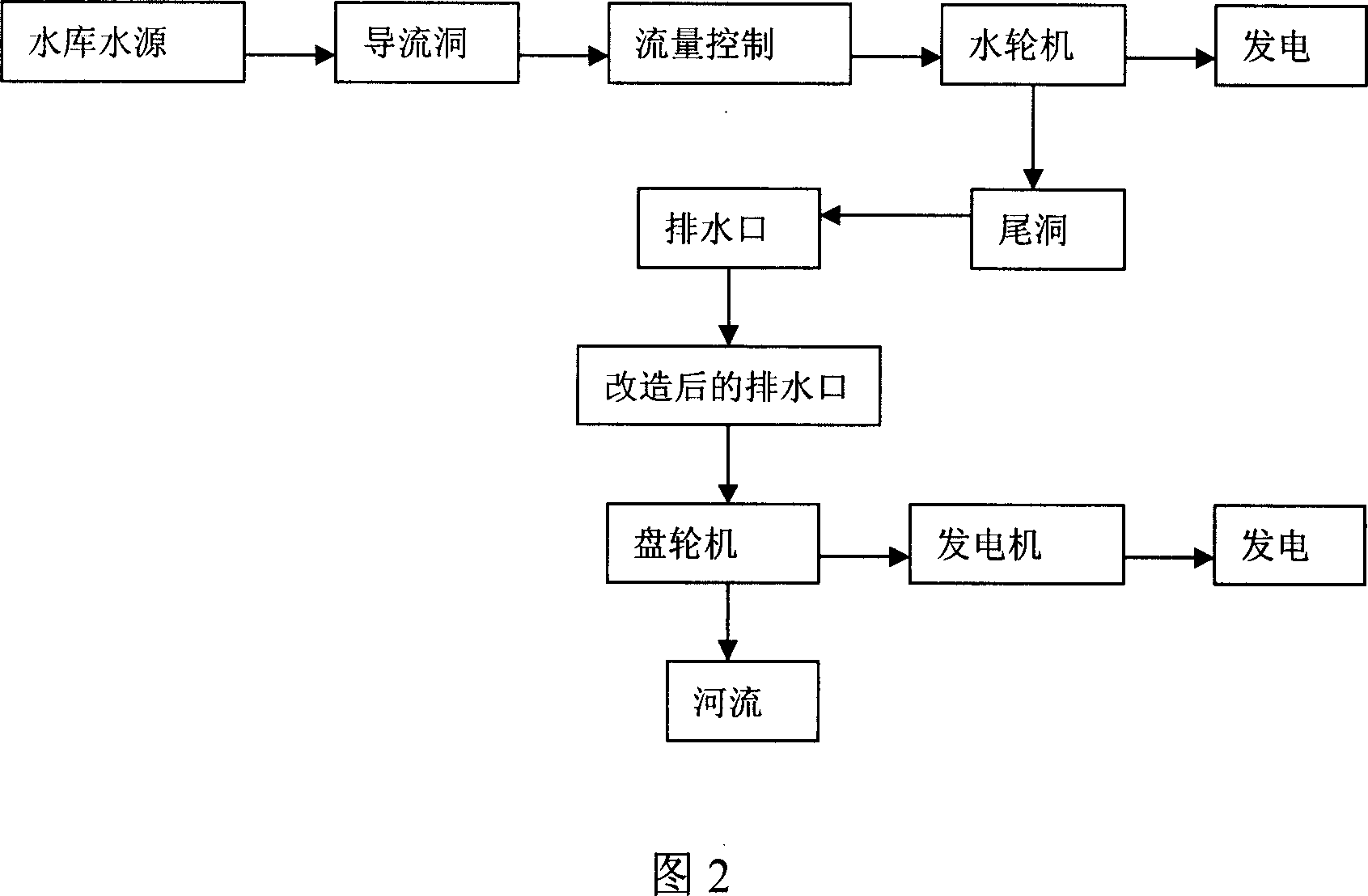
[0015] Fig. 2 is the process flow chart of the secondary utilization of water energy in the present invention. The water source of the reservoir enters the tail hole to the drain outlet after the water source is generated once through the water turbine through the diversion hole, and then the size of the tail hole outlet is determined according to the flow rate, and the water passes through the tail hole outlet. , punching the disk turbine to make the disk turbine rotate, the disk turbine drives the generator to generate electricity, and the water flowing through the disk turbine enters the river.

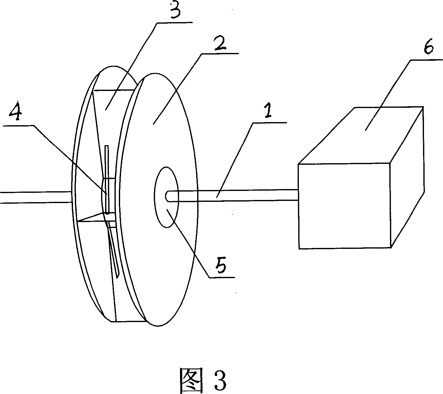
[0016] Fig. 3 is a schematic diagram of the structure of the disc wheel machine. The disc whe...


PUM


Abstract

A secondary using technology for residual energy of hydropower is disclosed. The discharged water after once electricity generation using can still generate biggish kinetic energy when flowing through an end cavity water discharging port, the size of the end cavity water discharging port can be determined by calculating the water discharging amount after once electricity generation using, a disk marine is mounted at the end cavity water discharging port, the discharged water flows through the disk marine to drive the generator to generate electricity, the discharged water flows from the disk marine then flows into rivers. The present invention mounts the disk marine at the end cavity water discharging port, makes the water after once electricity generation using can generate electricity for second time, the technics is simple and can be easily executed, it not only realize the object of increasing 60% of the electricity generation amount but also effectively prevent the harm of the residual energy.

Description

technical field [0001] The invention relates to a hydroelectric power generation process, in particular to a secondary utilization process of surplus energy of hydroelectric power generation and its device. Background technique [0002] At present, the technology of utilizing water resources to generate electricity in the world is that the water stored in the reservoir passes through the diversion hole and the control pipe, and the potential energy of the water is converted into kinetic energy to drive the hydro turbine to generate electricity. The water after power generation is discharged from the outlet through the tail hole. This causes waste of water energy flowing through the water turbine. Contents of the invention [0003] The technical problem to be solved by the present invention is to provide a process and a device for secondary utilization of residual energy of hydropower generation for secondary utilization of residual energy of water resources passing through...

Claims


Application Information

Patent Timeline
IPC IPC(8): F03B13/00
Inventor 常立
Owner 常立
Learn More