Timepiece assembly with world time zone display

A timing assembly, world time zone technology, applied to time indicating mechanical devices, mechanically driven clocks, and visual indication of time and other directions, which can solve difficulties in interpretation, inability to print world maps, and time and time gaps are tightened, etc. question

Inactive Publication Date: 2007-10-17
ATOP PRECISION IND CO LTD
View PDF1 Cites 6 Cited by
  • Summary
  • Abstract
  • Description
  • Claims
  • Application Information

AI Technical Summary

Problems solved by technology

The disadvantage is that the movement used must be 24 hours, and there is no positioning structure between the time zone ring and the clock face, so after a period of use, the time zone ring often becomes loose, which in turn causes difficulties in interpretation.
Furthermore, there is a certain distance between the time zone ring of the world clock and the 24-hour time scale, which is likely to cause errors in interpretation.
In particular, since the clock face must be equipped with 24-hour markings, the distance between the time and the time is shortened, which is not conducive to the interpretation of the minute hand
[0005] The watch is too thin and short, and the surface is limited in size, so that it is impossible to print a world map, so that you can check the time according to the map.
The current solution is to install two movements in the watch to display the time of the two places. However, in this way, the time in other time zones cannot be calculated immediately, rather than a comprehensive timing assembly for displaying world time zones. However, it is urgent to improve the relevant industry

Method used


Image

  • Timepiece assembly with world time zone display
  • Timepiece assembly with world time zone display
  • Timepiece assembly with world time zone display

Examples


Embodiment Construction

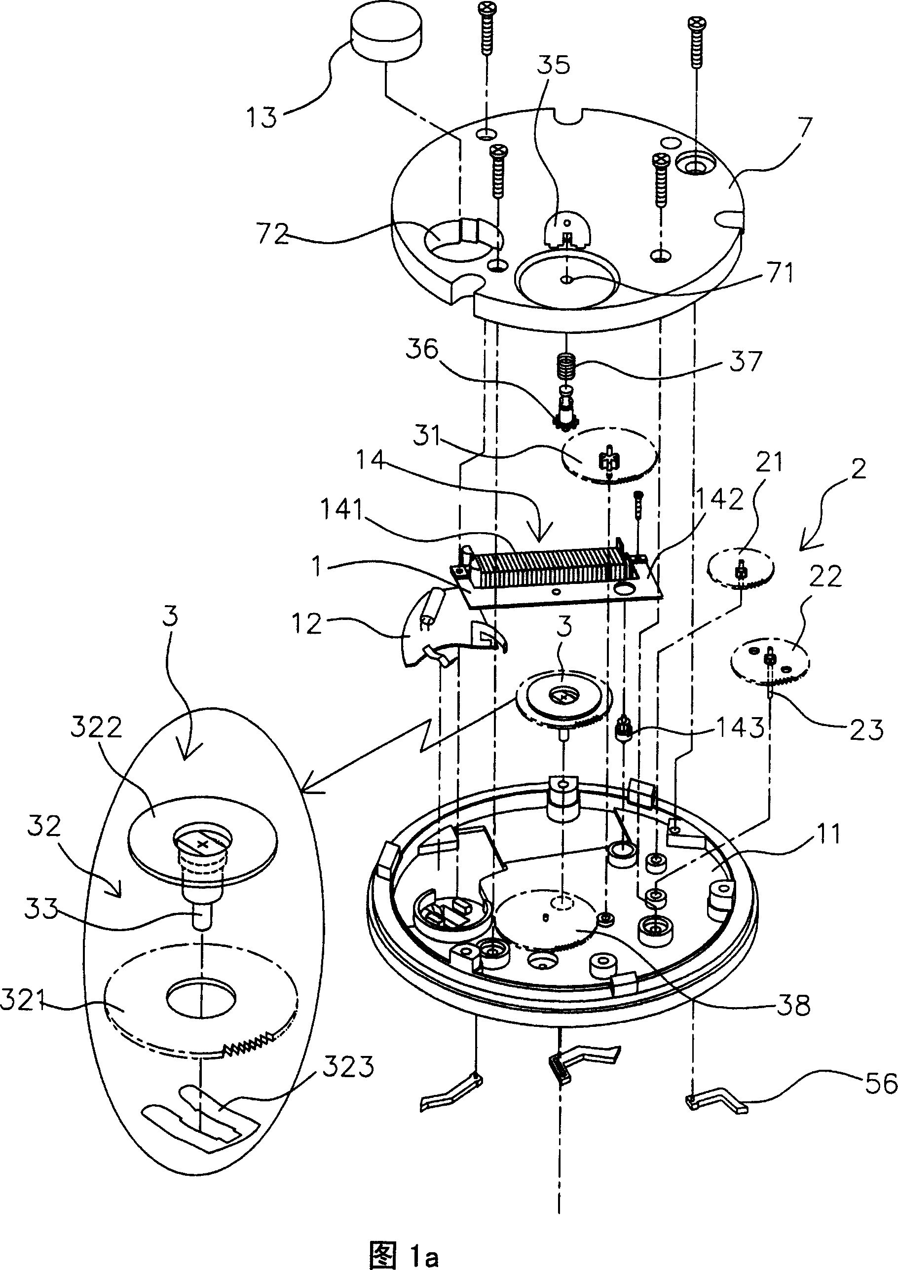
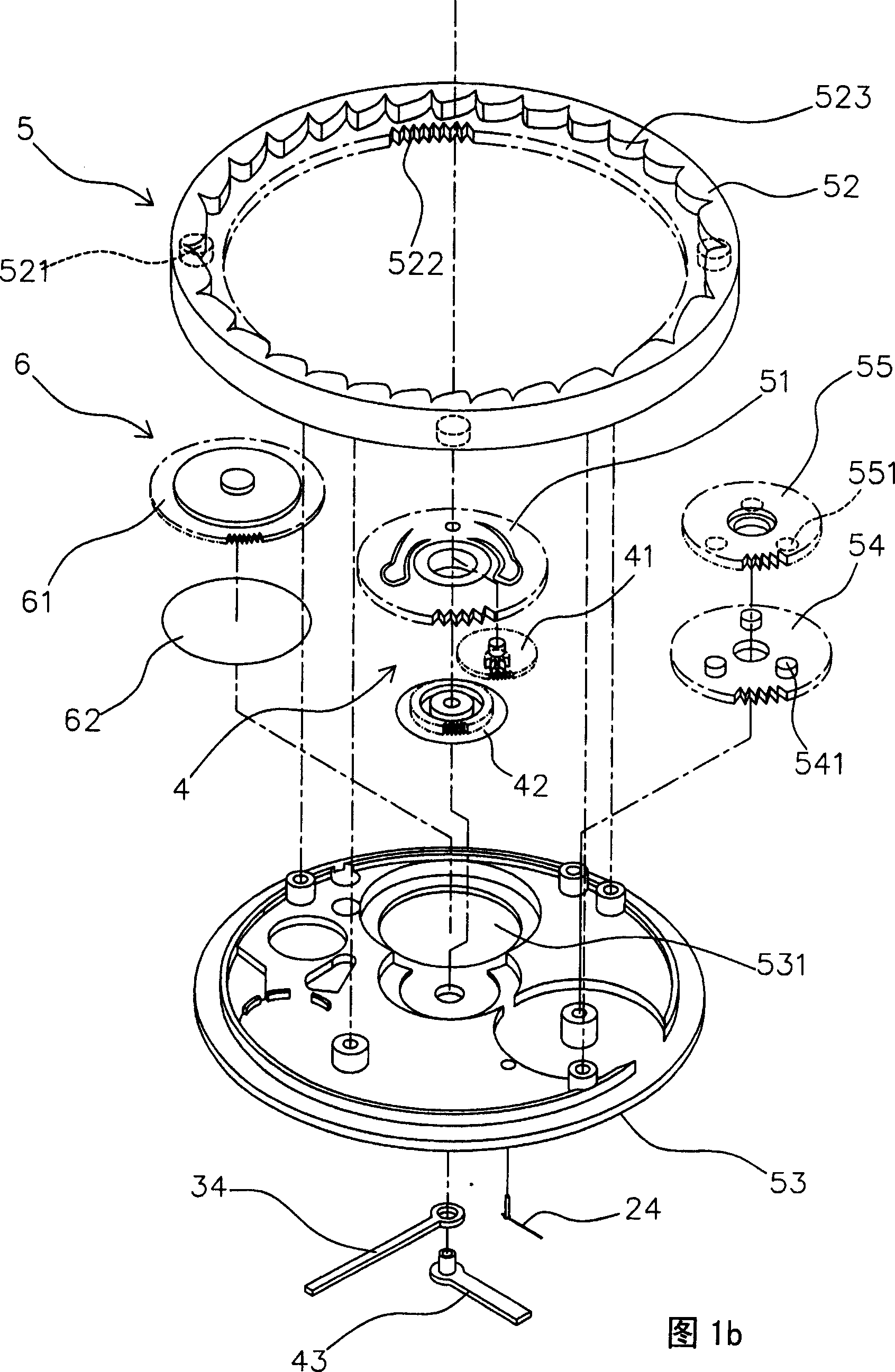
[0039]As shown in Figure 1a to Figure 4, basically, the timing assembly of the present invention is mainly composed of a power source 1, a second counting device 2, a scoring device 3, a timing device 4, and a time zone display device 5. Become. At the same time, the movement of the present invention may further include a day and night display device 6.

[0040] As shown in the figure, the power source 1 is fixed on a base 11, and a battery 13 is installed on a circuit board 12 to supply power to a well-known coil 141, a stator 142, and a rotor 143. The stepping motor 14 enables the rotor 143 to rotate at a constant speed and outputs power to the second counting device 2.

[0041] The seconds device 2 is pivotally connected to the base plate 11 by the one-second front wheel 21 and meshes with the rotor 143 to move therewith. The other side meshes with the one-second wheel 22 so that the seconds shaft 23 below it rotates 360 degrees per minute. . Furthermore, the second shaft 23 pr...


PUM


Abstract

A time counting assembly capable of displaying world time zones is composed of a power source, a second counting device, a minute counting device, an hour counting device and a time zone display device, and can display correct time on a panel; wherein, the time zone adjusting ring of the time zone display device is clamped between a base seat and a panel and is at rotatable status, a planet idle gear between the base seat and the panel is engaged with the ring tooth part of the time zone adjusting ring and a planet base gear connected to the central part of the bottom of the base seat, the planet base gear is supplied to pass the divide gear group of the minute counting device, and the front wheel of the hour counting device is pivoted to on side of the bottom of the planet base gear, the circumferential edge of the base seat is at least connected with two elastic buckle claws that buckle to several spinous holes arranged on the top of the time zone adjusting ring in a ring shape; the time zone adjusting ring is dialed to make its ring tooth part drive the planet idle gear and the planet base gear rotate, and the hour front gear is moving on the planet base gear, the planet base gear is driven to rotate with an engaged hour hand to move the hour hand to the time of a second ground mark.

Description

Technical field [0001] The invention relates to a timing assembly, in particular to a timing assembly with a world time zone display. Background technique [0002] With the development of transportation and communications, international exchanges have become more frequent, and cross-border exchanges have become more common. Based on the consideration of information transmission and time difference, it is possible to display the timing assembly of other time zones at the same time, such as clocks (or clocks). Called the world clock) or watches came into being. [0003] The most common known world clock is to print a world map on the clock face, and then check the time according to the map. The disadvantage of this method is that the clock face is too complicated and does not conform to ergonomics in terms of visual cognition and communication. [0004] Take a simple world clock as an example. It uses a 24-hour movement as the time display, and its clock face is fitted with a time ...

Claims


Application Information

Patent Timeline
Patent Type & Authority Applications(China)
IPC IPC(8): G04B19/22G04B19/02G04B33/08G04C3/00G04C3/14G04C10/00
Inventor 林文传
Owner ATOP PRECISION IND CO LTD
Why Eureka
Try Eureka