
Method for controlling fan rotation speed of electronic system and system for implementing the method

A fan speed and electronic control technology, applied in control/regulation systems, non-electric variable control, speed/acceleration control, etc., can solve the problem of the minimum fan speed that cannot be grasped in real time when the CPU temperature changes, and cannot design the basic heat dissipation requirements of the CPU , It is impossible to predict the type of heat dissipation module of the motherboard and other problems

Inactive Publication Date: 2007-10-17
LITE ON TECH CORP
View PDF0 Cites 13 Cited by
  • Summary
  • Abstract
  • Description
  • Claims
  • Application Information

AI Technical Summary

Problems solved by technology

However, when it is shipped as a motherboard, the manufacturer cannot predict the type of cooling module that the motherboard will be equipped with and the ambient temperature in which it will operate, so it is impossible to design a formula for the minimum fan speed to maintain the basic cooling requirements of the CPU
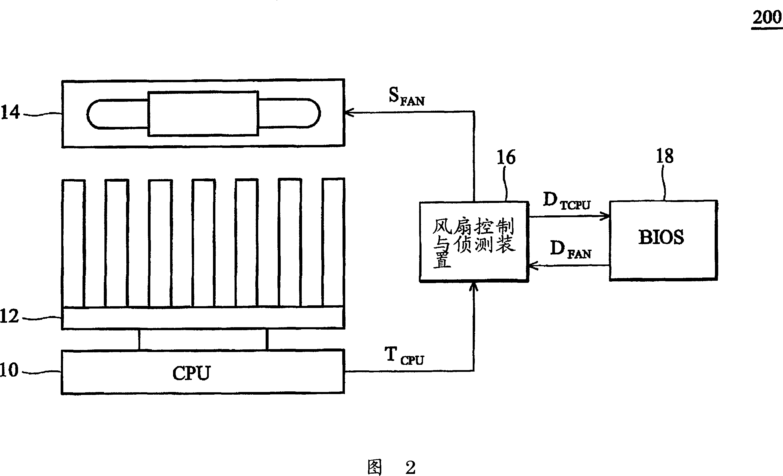
In addition, because the fan control and detection device 16 first detects the CPU temperature and then starts to adjust the fan speed, it is impossible to grasp the temperature change of the CPU in real time.

Method used


Image

  • Method for controlling fan rotation speed of electronic system and system for implementing the method
  • Method for controlling fan rotation speed of electronic system and system for implementing the method
  • Method for controlling fan rotation speed of electronic system and system for implementing the method

Examples


Embodiment Construction

[0046] In order to make the features, objects and advantages of the present invention more comprehensible, preferred embodiments will be described in detail below together with the accompanying drawings.

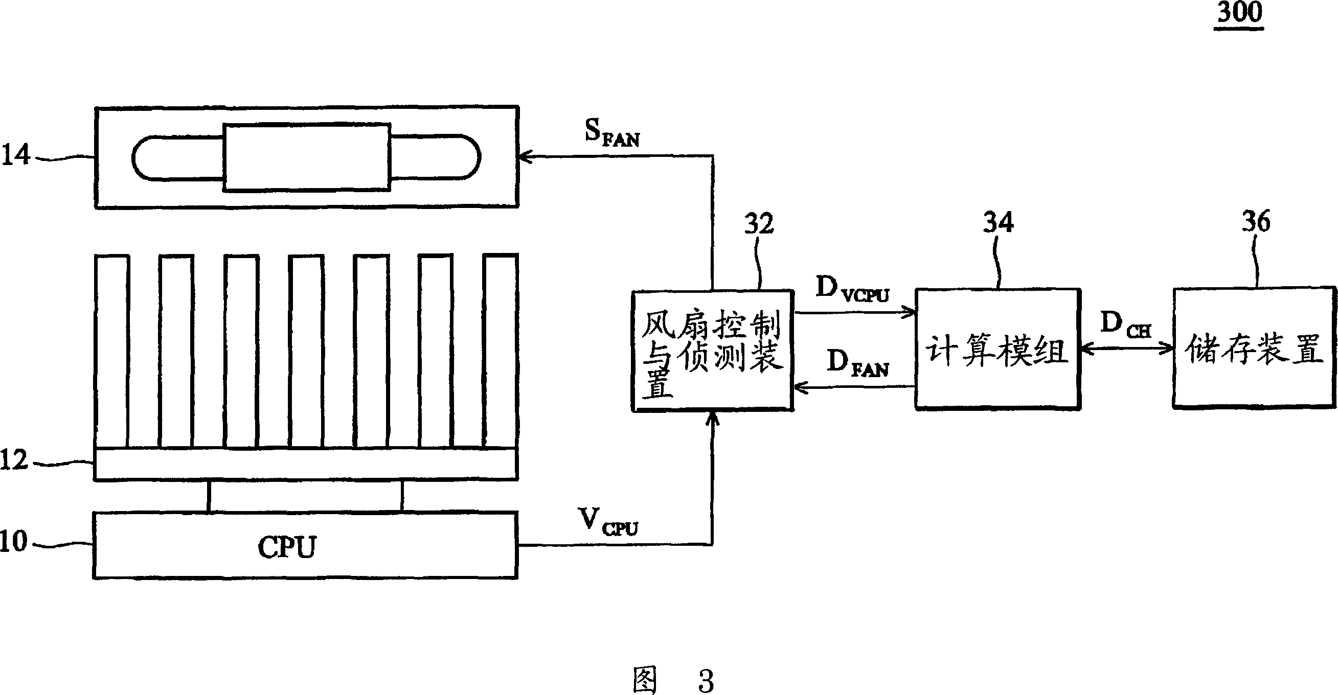
[0047] FIG. 3 is an embodiment of the structure diagram of the electronic system provided by the present invention. The electronic system 300 includes a CPU 10, a heat sink 12 and a heat dissipation fan 14, both of which constitute a heat dissipation module to assist the heat dissipation of the CPU 10, a fan control and detection device 32 is coupled to the CPU 10 and the heat dissipation fan 14, A calculation module 34 is coupled to the fan control and detection device 32, and a storage device 36 for storing system characteristic data D CH . System characteristic data D CH , for example, is the heat dissipation efficiency parameter of the heat dissipation module, and the ambient temperature in the electronic system. The computing module 34, for example, can be formed by ...


PUM


Abstract

The present invention provides a method for controlling the rotate speed of the fan in an electronic system and a system for applying the method, wherein the electronic system includes a CPU and a heat radiation model set composed of a heat radiating fan and heat radiating fins. The method includes: measuring the kernel voltage of the CPU to obtain the power of the CPU, obtaining a first wait correcting fan rotate speed based on the power of the CPU, and correcting the first wait correcting fan rotate speed based on the characteristic data of the electronic system. The invention chooses the power generated during the operation of the CPU as the main criterion for adjusting the rotate speed of the fan, therefore the rotate speed of the fan can be adjusted in time based on the executing condition of the CPU. The invention is able to correct the rotate speed of the heat radiating fan based on the characteristic of the system, and can maintain basic heat radiating requirement of the CPU and the best control for the rotate speed of the fan even the CPU is matted with different heat radiating set and runs under different environmental temperature.

Description

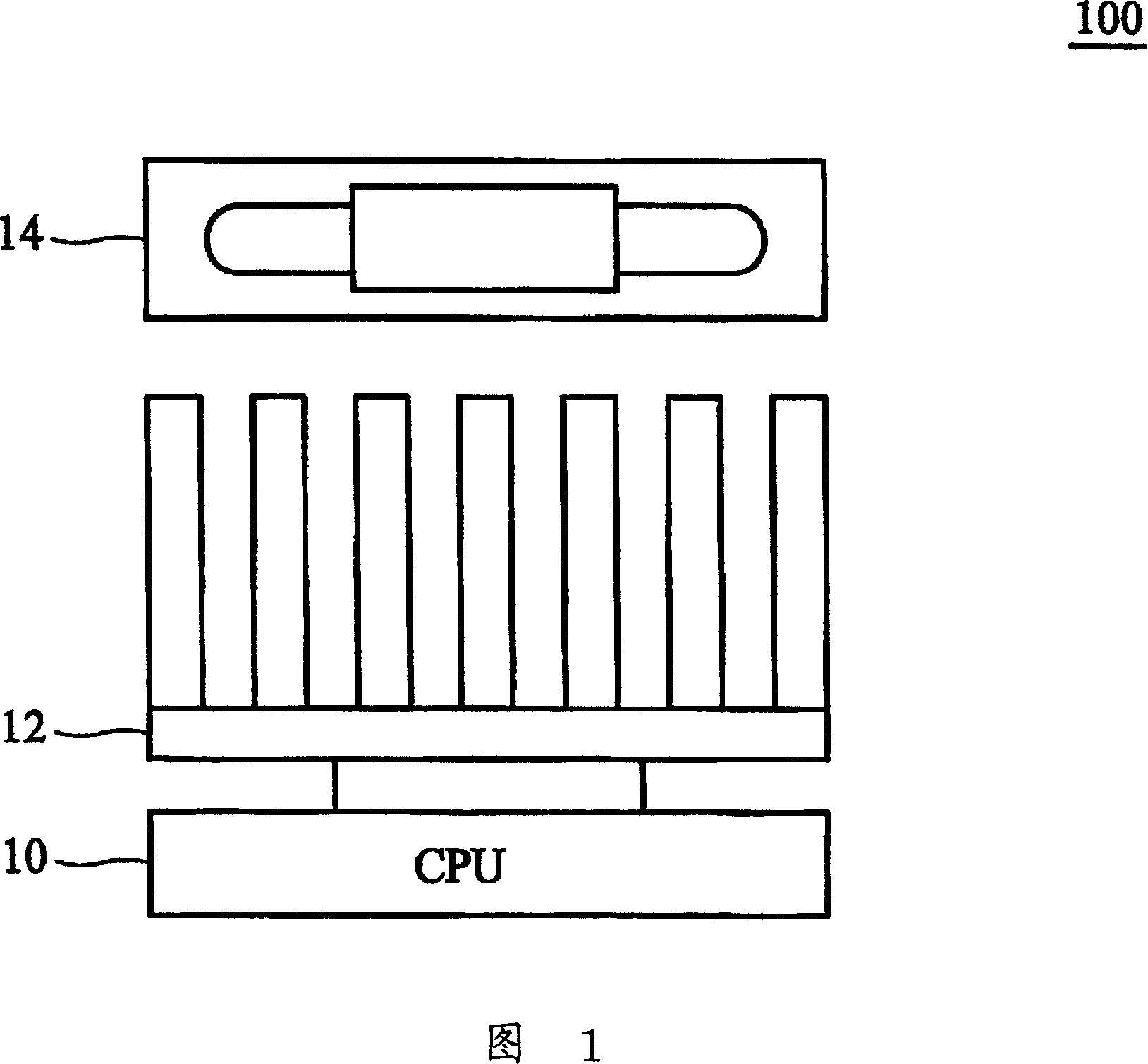
technical field [0001] The present invention relates to a heat dissipation method of an electronic system, and in particular to a method for controlling a heat dissipation fan in the electronic system and a system using the method. Background technique [0002] FIG. 1 is a block diagram showing a conventional computer electronic system. The electronic system 100 includes a CPU 10 , a heat sink 12 , and a cooling fan 14 . Since the CPU 10 will generate heat during operation and cause temperature rise, in order to prevent the CPU 10 from being damaged by overheating, the heat sink 12 and the diffuser fan 14 form a heat dissipation module to assist in the dissipation of heat. The electronic system does not include any fan control device to control the speed of the cooling fan 14 , that is, the cooling fan runs at the same speed regardless of the execution speed of the CPU 10 at that time. However, in order to cope with the possible high execution speed of the CPU 10 , the spe...

Claims


Application Information

Patent Timeline
IPC IPC(8): G05D13/66G12B15/00
Inventor 吕明祐
Owner LITE ON TECH CORP
Learn More