Heat dispersion connector

A heat-dissipating and joint technology, applied in the direction of connection, conductive connection, electrical component connection, etc., can solve the problems of high cost of converting fittings, burning of busbars, and fires, etc., to achieve light weight, increase heat dissipation space, and reduce fire. heat effect

Active Publication Date: 2007-10-17
广东日昭新技术应用有限公司
View PDF1 Cites 7 Cited by
  • Summary
  • Abstract
  • Description
  • Claims
  • Application Information

AI Technical Summary

Problems solved by technology

[0002] The existing conductive pipe busbar joint (patent number: 01215457.1) has the following disadvantages in the actual installation process: since the conductive pipe busbar is circular, it is necessary to install conversion fittings during the connection with the equipment, from a round surface to a plane, through Rectangular conductors to connect with other equipment
1. The connection between the pipe busbar and the equipment needs to be equipped with conversion fittings, which is costly, wastes materials, and consumes energy
2. The connection between the end of the pipe busbar and the conversion fitting will generate contact resistance. Due to the existence of contact resistance, in the case of high current transmission, the end of the pipe busbar and the conversion fitting will generate excessive heat. The greater the heat, the higher the resistance , the more serious the heat is, the higher the temperature will cause the pipe busbar to be blown, short circuit between phases, short circuit to ground or cause a fire and cause a greater accident

Method used


Image

  • Heat dispersion connector
  • Heat dispersion connector
  • Heat dispersion connector

Examples


Embodiment Construction

[0018] The specific embodiments of the present invention will be further described below in conjunction with the accompanying drawings.

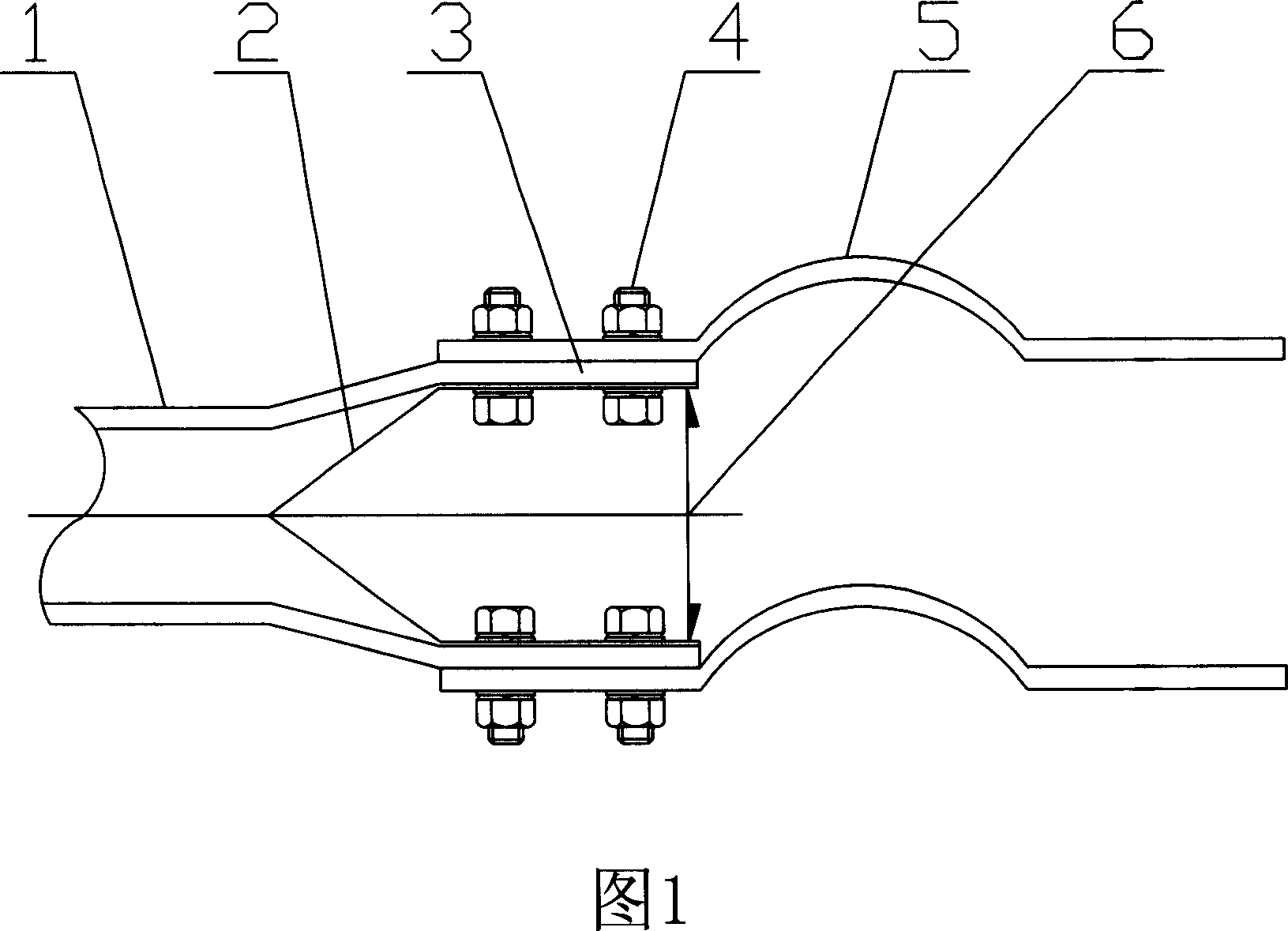
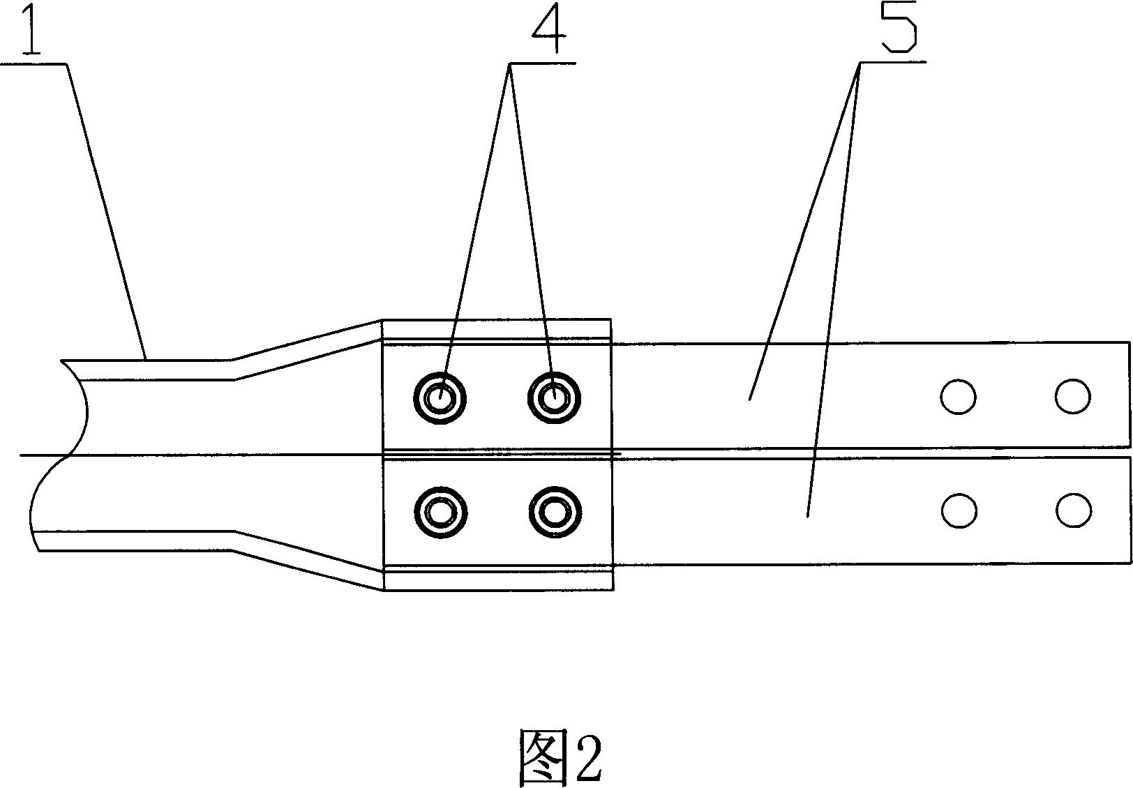
[0019] As shown in Fig. 1 and Fig. 2, the first embodiment of the present invention is to divide the end of the pipe busbar with a diameter of Φ30mm to 500mm and a wall thickness of 1mm to 30mm (the length of about twice the diameter of the pipe busbar) into two semicircles, Then the two semicircles are punched into two conductive surfaces by stamping process. There are reinforcing ribs on both sides of the two conductive surfaces, and there is a certain heat dissipation space between the two conductive surfaces. Or soft connection is connected with other equipment, which forms a heat-dissipating heat-dissipating joint.

[0020] As shown in Figure 6 and Figure 7, the second specific embodiment of the present invention is to use a punch press or a hydraulic press to form four conductive surfaces with a diameter of Φ30mm to 500mm and a wall th...


PUM


Abstract

The pipe bus end of the inventive heat radiating type joint and the heat radiating type joint an integrated one. The pipe bus end has a plurality of conducting surfaces, and there is a certain distance between the conducting surface and the conducting surface, so that: 1. It is easy to connect with other equipments; 2. it increases the heat-radiating space; 3. It is helpful to reduce the temperature rise of the end joint; 4. since it is an integrated one withou link bit and contacting resistance, thus reducing the heat, has a large carrying capacity, and ensures the end of the bus will not have a high temperature, and will have safe operation; 5. Since the heat radiating type joint is an integrated one which has canceled original conversion gold, so that it is low cost, light weight, and energy savings.

Description

technical field [0001] The heat-dissipating joint of the invention is especially suitable for connecting the busbars of conductive pipes that transmit power-frequency and large currents. Large current carrying capacity, low temperature rise, high mechanical strength, and improved operating safety factor. Background technique [0002] The existing conductive pipe busbar joint (patent number: 01215457.1) has the following disadvantages in the actual installation process: since the conductive pipe busbar is circular, it is necessary to install conversion fittings during the connection process with the equipment, from a round surface to a plane, through Rectangular conductors connect with other devices. 1. It is necessary to install conversion fittings to connect the pipe busbar to the equipment, which is costly, wastes materials and consumes energy. 2. The connection between the end of the pipe busbar and the conversion fitting will generate contact re...

Claims


Application Information

Patent Timeline
Patent Type & Authority Applications(China)
IPC IPC(8): H01R4/46H01R11/00
Inventor 罗东豪
Owner 广东日昭新技术应用有限公司
Why Eureka
Try Eureka