
Non symmetrical interleaving mixed exciting synchronization motor

A hybrid excitation synchronous and asymmetrical technology, applied in the field of hybrid excitation synchronous motors and improved motors, can solve the problems of limited installation space of the excitation winding, increase the axial length of the motor, reduce the utilization rate of materials, etc., and achieve obvious magnetic adjustment effect, The effect of improving the efficiency of electric excitation and avoiding irreversible demagnetization

Inactive Publication Date: 2007-10-17
SOUTHEAST UNIV
View PDF0 Cites 15 Cited by
  • Summary
  • Abstract
  • Description
  • Claims
  • Application Information

AI Technical Summary

Problems solved by technology

However, its excitation winding is installed on the outer stator, resulting in a longer length of each turn, greater winding resistance, and more electrical excitation loss; secondly, the installation space of its excitation winding is extremely limited, and it is necessary to increase the proportion of electrical excitation to increase The axial length of the motor reduces the utilization rate of materials

Method used


Image

  • Non symmetrical interleaving mixed exciting synchronization motor
  • Non symmetrical interleaving mixed exciting synchronization motor
  • Non symmetrical interleaving mixed exciting synchronization motor

Examples


Embodiment Construction

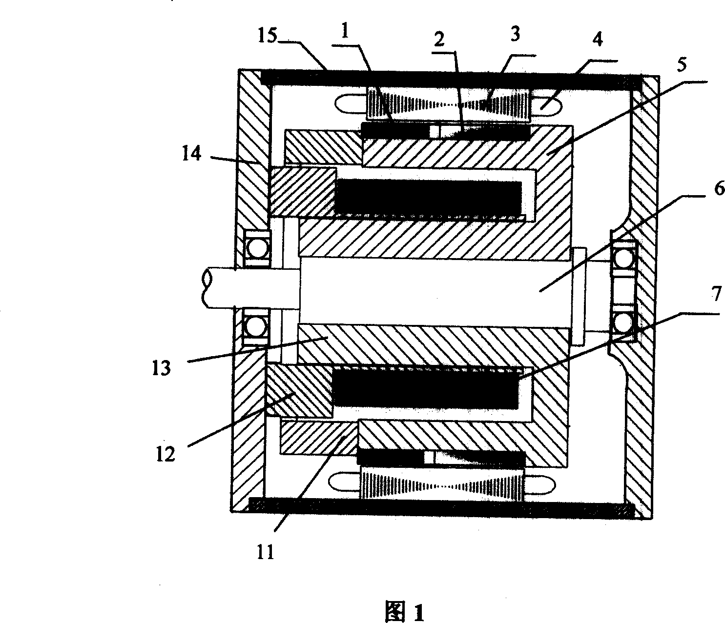
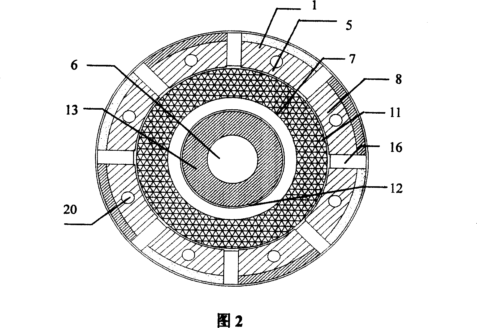
[0025] The outer stator of the motor is similar to the stator of an ordinary motor, with multi-phase symmetrical armature windings 4 embedded in the slots, and a ring-shaped excitation winding 7 placed on the inner stator of the motor. The field winding 7 is fixed on the motor end cover 14 via a magnetically conductive yoke bracket 12 . Since the excitation winding 7 is placed in the area formed by the inner and outer units of the tile-shaped claw poles, the space utilization rate is high and the structure is compact. The excitation winding 7 is placed inside the rotor, so that each turn of the excitation coil is greatly shortened, thereby reducing the resistance and excitation loss of the excitation winding 7, and improving the efficiency of the motor. In addition, due to the large internal space of the rotor, more excitation coils can be accommodated.

[0026] The use of tile-shaped claw poles facilitates processing and greatly simplifies the manufacturing process.

[0027...


PUM


Abstract

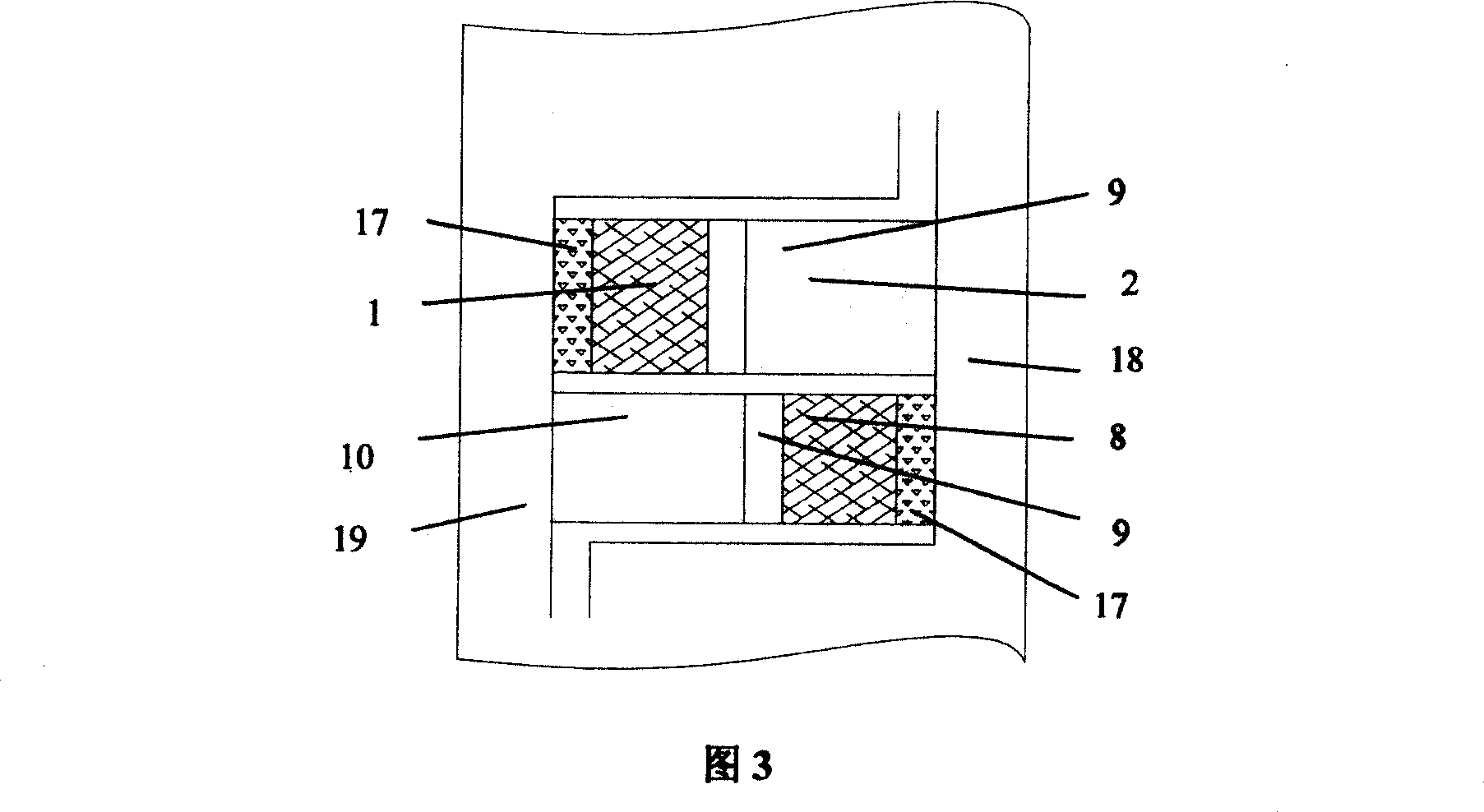
The present invention provides an unsymmetrical, crossly mixed excitation synchronous motor pertaining to the technology field of electric motor for variable-speed driving. The technology problem to be solved is: a new type mixed excitation synchronous motor which has been improved to have a higher efficiency, a bigger low-speed starting torque and a wider timing range. The motor in the present invention adopts a structure with an internal stator and an external stator. A stator back yoke (15) for magnetic guiding in the axes direction of a stator is provided out of a stator, adopting a unique tile shaped structure which is easy to process. The external stator is identical to the traditional stator of the electric motor, and the ring shaped field copper (7) is fixed on the end cover (14) of the electric motor to form an internal stator through a field yoke bracket (12). The thickness of the Claw-Pole (5) of the N pole is identical to that of the Claw-Pole (11) of the S pole, and the permanent-magnet pole (1) and the magnet core pole (2) of the N pole are adhered on the surface of the Claw-Pole of the N pole, and are separated by an air gap (9) for separating the magnet; the permanent-magnet pole (8) and the magnet core pole (10) of the S pole are adhered on the surface of the Claw-Pole of the S pole, and are separated by an air gap (9) for separating the magnet.

Description

technical field [0001] The invention relates to an improved motor, in particular to a hybrid excitation synchronous motor with high efficiency, low speed, large starting torque, wide speed regulation and direct drive, and belongs to the technical field of motor manufacturing. Background technique [0002] There is no winding on the rotor of the permanent magnet motor, and there is no excitation loss, so it works reliably and has high efficiency, but the difficulty in adjusting the permanent magnet magnetic field limits its application. Combining permanent magnet and electric excitation rationally, researching and developing a hybrid excitation motor that not only integrates the advantages of electric excitation motor and permanent magnet excitation motor, but also overcomes their respective defects, so as to maximize the advantages of both, and become the motor field an important research topic. [0003] Due to its adjustable magnetic flux, the hybrid excitation motor can r...

Claims


Application Information

Patent Timeline
Patent Type & Authority Applications(China)
IPC IPC(8): H02K19/12H02K1/06H02K1/27
Inventor 林鹤云杨成峰
Owner SOUTHEAST UNIV
Learn More