Control valve type lead battery

A lead-acid battery, valve-controlled technology, applied in secondary batteries, battery pack parts, battery caps/end caps, etc. high effect

Inactive Publication Date: 2007-10-17
PANASONIC CORP
View PDF1 Cites 3 Cited by
  • Summary
  • Abstract
  • Description
  • Claims
  • Application Information

AI Technical Summary

Problems solved by technology

[0016] However, in the prior art lead-acid storage battery in which the vent hole 52 at the bottom of the vent chamber 51 is covered by the valve body 53 as shown in FIG. Stiction has a greater impact on the operation of safety valves and thus poses difficulties in maintaining the reliability of lead-acid batteries

Method used


Image

  • Control valve type lead battery
  • Control valve type lead battery
  • Control valve type lead battery

Examples


Embodiment 1

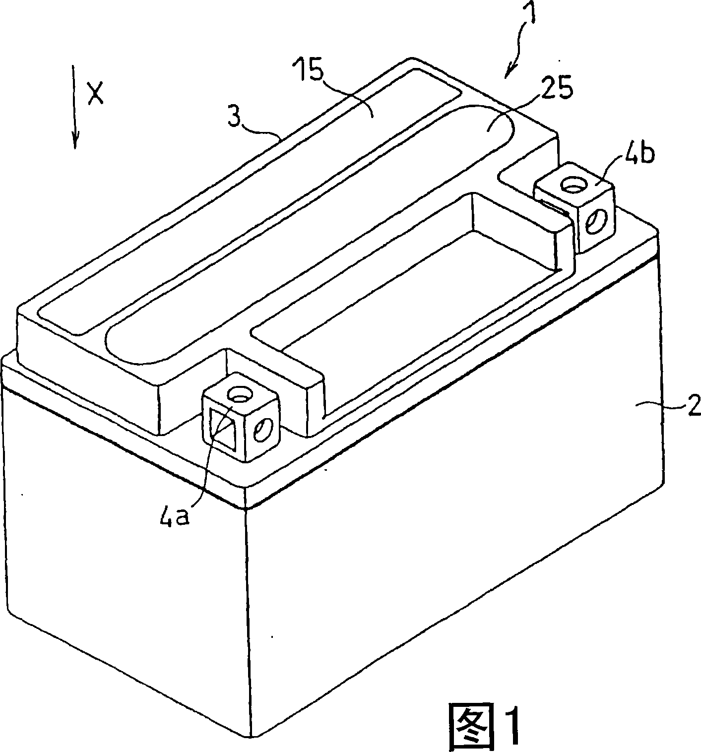
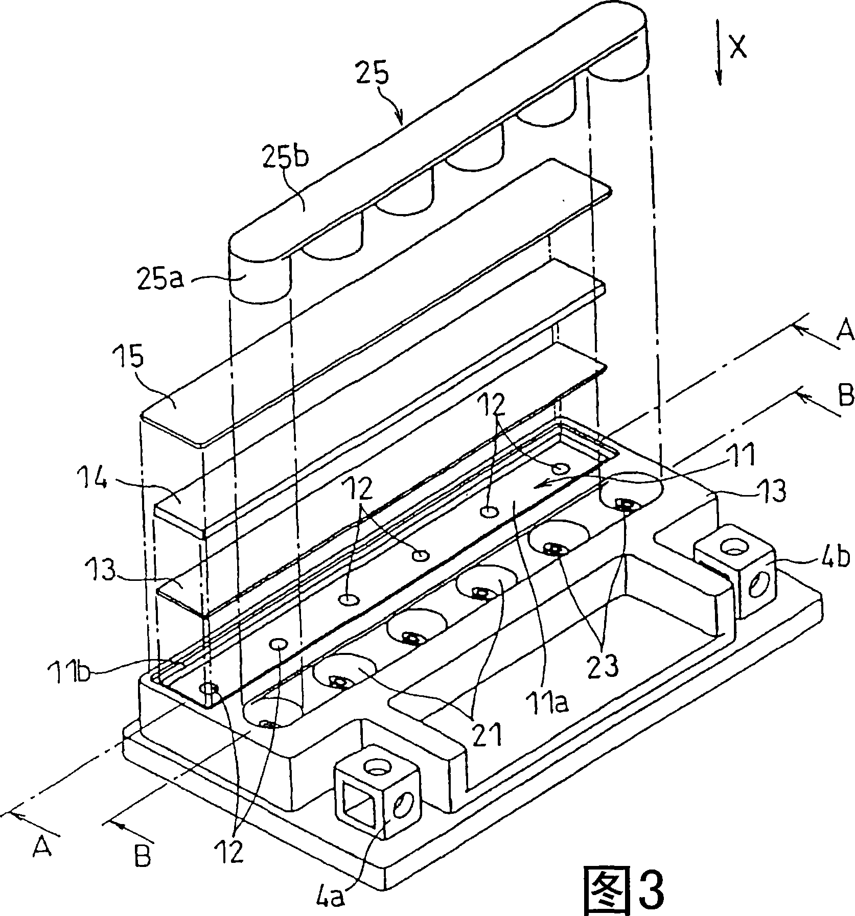
[0105] In this example, a lead-acid storage battery A (12V-6Ah) of the present invention using the battery cover 3 having the structure shown in FIGS. 1-6 of the above-described embodiment was manufactured.

[0106] The plate-shaped valve body 13 serving as a safety valve was manufactured using neoprene (having a thickness of 0.3 mm and an international rubber hardness of 60 degrees). Sheet 14 was fabricated from EPDM foam (thickness 2.0 mm) with a void ratio of 90%. Furthermore, after fixing the top plate 15 to the battery cover 3 in battery manufacture, the thickness of the sheet 14 was set at 1.4 mm when compressed. Therefore, the sum of the thickness of the valve body 13 and the thickness of the sheet 14 at the time of manufacturing the battery was 1.7 mm. In addition, silicone oil is applied to the surface of the valve body 13 that is in contact with the bottom 11 a of the exhaust chamber 11 .

[0107] In the manufacture of the electrode plate group, each positive elect...


PUM

PropertyMeasurementUnit
hardnessaaaaaaaaaa

Abstract

The present invention provides a control valve type lead battery comprising a battery jar provided with a plurality of cells, and a battery lid fixed to the opening of the battery jar. The battery lid comprises an exhaust chamber having in the bottom, an exhaust opening communicating with the cell, and a liquid injection chamber having in the bottom a liquid injection opening communicating with the cell. The exhaust chamber comprises a platy valve element butting against the bottom of the exhaust chamber and covering the exhaust opening, a resilient sheet arranged on the valve element, and an upper plate secured to the battery lid and covering the sheet. The liquid injection chamber is provided with a plug for closing the liquid injection opening.

Description

technical field [0001] This invention relates to valve-regulated lead-acid batteries, and in particular to the structure of the battery cover. Background technique [0002] In recent years, valve-regulated lead-acid batteries (sealed lead-acid batteries) including a separator composed of glass fibers holding an electrolyte and a negative plate for absorbing oxygen generated during charging have been widely used. Generally, such lead-acid batteries include a battery well with a plurality of batteries and a battery cover for covering and sealing the opening of the battery well. Each of the above-mentioned batteries contains an electrode plate group composed of alternately arranged positive plates and negative plates, and a separator is arranged between the positive plates and the negative plates. Then, open and close the safety valve provided in the battery cover to regulate the gas pressure in the battery. [0003] Fig. 10 is an exploded perspective vi...

Claims


Application Information

Patent Timeline
Patent Type & Authority Applications(China)
IPC IPC(8): H01M2/12H01M2/04H01M2/08H01M2/36H01M50/147H01M50/627
CPCH01M10/121H01M2/362H01M2/1288H01M2/043Y02E60/126H01M2/1235Y02E60/10H01M50/147H01M50/342H01M50/627H01M50/183H01M50/60
Inventor 青木伸之铃木芳江
Owner PANASONIC CORP
Why Eureka
Try Eureka