
Pedal control gem shaping machine

A control type, setting machine technology, used in manufacturing tools, machine tools suitable for grinding workpiece edges, grinding machines, etc., can solve the problem of retrofitting and retrofitting of pedal-type floor adjustment devices, unfavorable renewal of existing equipment, and large investment costs. problems, to achieve the effect of improving production efficiency and economic benefits, reducing industrial accidents, and improving production efficiency

Inactive Publication Date: 2007-10-24
何伟坚 +3
View PDF1 Cites 4 Cited by
  • Summary
  • Abstract
  • Description
  • Claims
  • Application Information

AI Technical Summary

Problems solved by technology

However, there are certain defects in this utility model patent. Its foot-operated platform adjustment device cannot be retrofitted on existing equipment. It is necessary to redesign and manufacture the mold of the gem grinding machine, and the whole set of equipment is re-produced, which is not conducive to the existing equipment. The update of equipment requires a large investment cost and is difficult to widely promote

Method used


Image

  • Pedal control gem shaping machine
  • Pedal control gem shaping machine
  • Pedal control gem shaping machine

Examples


Embodiment 1

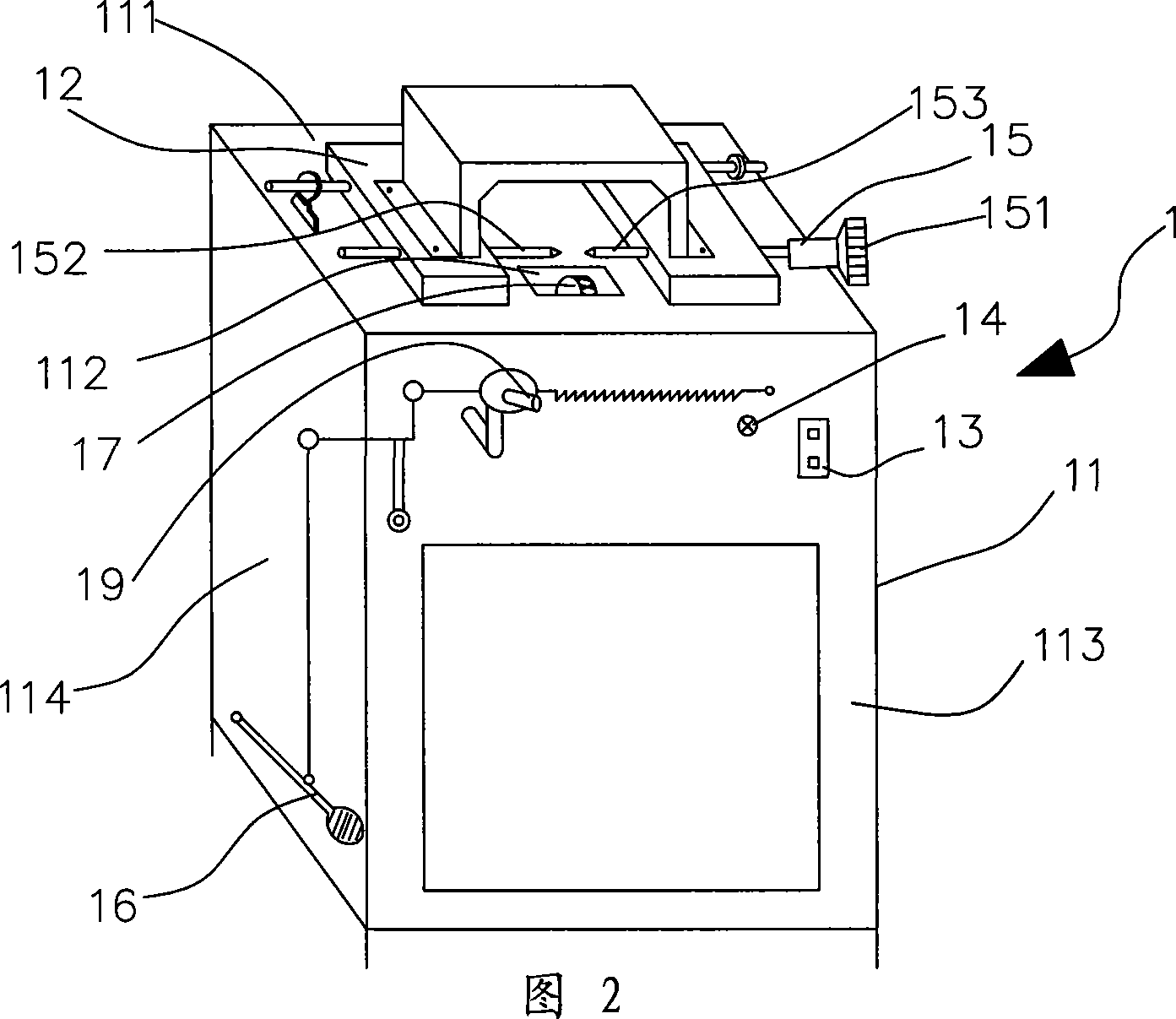
[0023] As shown in Figure 4, the pedal-controlled gem setting machine 1 of the present invention includes a base 11, a grinding wheel 17 installed inside the notch 112 on the upper surface 111 of the base 11, and a machine head installed on the upper surface 111 of the base 11. 12. The machine head lifting operation lever 19 for directly controlling the height of the machine head, the switch 13 and the indicator light 14 arranged on the front surface 113 of the base 11, the advance and retreat mechanism 15 for clamping the workpiece, and the mechanism for controlling the up and down movement of the machine head 12 Pedal toggle mechanism 16.

[0024] The advancing and retreating mechanism 15 includes a left shaft 152 of the shaping machine, a right shaft 153 of the shaping machine and an advancing and retreating handle 151, and the workpiece is clamped between the left shaft 152 of the shaping machine and the right shaft 153 of the shaping machine.

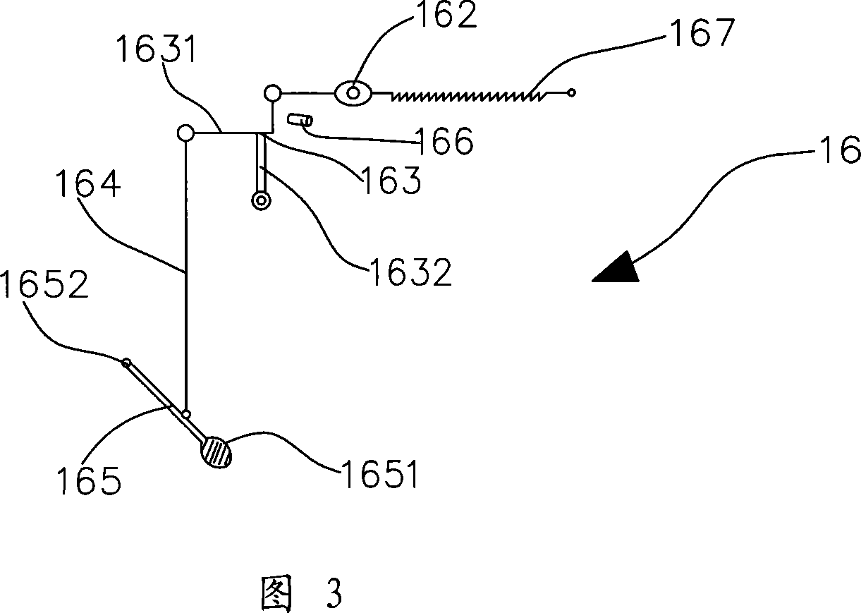
[0025] The pedal toggle mec...

Embodiment 2

[0029] As shown in Figure 4 and Figure 5, as another embodiment of the present invention, other parts are the same as in Embodiment 1, the difference is:

[0030] The pedal toggling mechanism 36 is arranged on the outside of the base 11 except the pedal 365, and all other components are arranged on the inside of the base 11. Such a pedal-controlled gem setting machine 1 has a simple and beautiful appearance.

[0031] Pedal toggling mechanism 36 comprises pedal 365, pedal sleeve 362, puller puller bar 364, location code one 3662, soft cable 3665, location code two 3667, cable lug 3669, mechanical handle 367, eccentric lifting shaft 368 and return spring 369. Wherein, a cam 3688 is fixed on the eccentric lifting shaft 368, and the return spring 369 is a scroll spring or a torsion spring fixed on the eccentric lifting shaft 368.

[0032] During use, the movement of the pedal 365 will pull the soft cable 3665, and the soft cable 3665 will make the mechanical pull handle 367 rotat...


PUM


Abstract

The pedal control marble positioning machine comprises the base, sand wheel, locomotive, locomotive alight operation lever and back and forth structure. It also comprises the tumbler device that is composed of tumbler plate, return spring connected to one side of the tumbler plate, motor directing machine connected to the end side of the tumbler plate, pedal fixed to the bottom of the base, pulling line connected to the motor directing machine and the pedal and the return controller, locomotive alighting operation bar installed inside the central hole, return spring not fixed to the base with the tumbler plate, nor of the drive directing machine and the tumbler plate. It is simple in process, operation and low in cost, with reasonable distribution, safe operation, reduced operation time, production cost and improved working efficiency and economical returns with ensured production quality.

Description

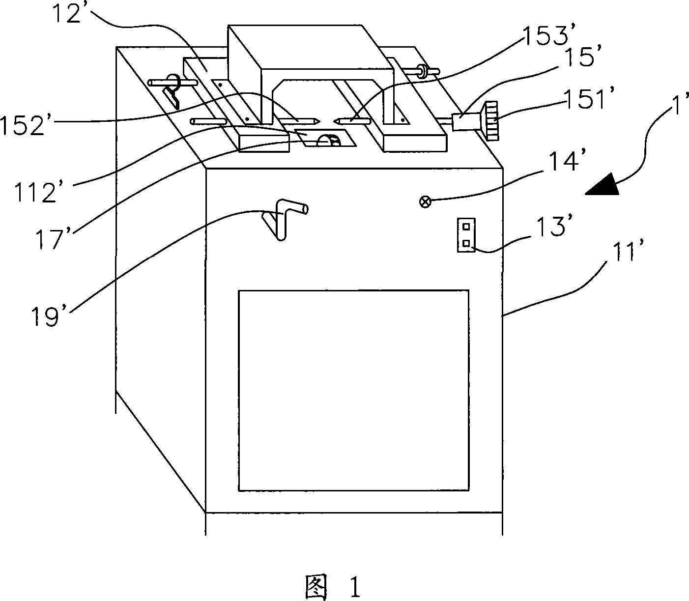
technical field [0001] The invention relates to a gem setting machine, in particular to a pedal-controlled gem setting machine. Background technique [0002] As shown in Figure 1, the existing gem setting machine 1 'comprises a base 11', a grinding wheel 17' installed on the inner side of the notch 112' on the upper surface of the base 11', and a machine mounted on the upper surface of the base 11'. The head 12', the switch 13' and the indicator light 14' arranged on the surface of the base 11', the advancing and retreating mechanism 15' for clamping the workpiece (usually stone), and the lifting operation of the machine head to control the up and down movement of the machine head 12' Rod 19'. The advancing and retreating mechanism 15' comprises a setting machine left shaft 152', a setting machine right shaft 153' and an advancing and retreating handle 151'. During processing, the workpiece is placed between the left shaft 152' of the shaping machine and the right shaft 15...

Claims


Application Information

Patent Timeline
Patent Type & Authority Applications(China)
IPC IPC(8): B24B9/16
Inventor 何伟坚李双全杨元庆林日新
Owner 何伟坚
Learn More