Liquefied natural gas storage tank having improved insulation structure and method of manufacturing the same

A technology of liquefied natural gas and isolation structure, which is applied in the field of liquefied natural gas storage tanks, can solve the problems of complicated structure of second sealing wall connection, complicated configuration of the separation wall, and reduced sealing reliability of the second sealing wall, etc., so as to increase the sealing reliability. , Easy assembly work, the effect of solving leakage problems

Active Publication Date: 2007-10-24
KC LNG TECH CO LTD ENTIRE RIGHT
View PDF8 Cites 10 Cited by
  • Summary
  • Abstract
  • Description
  • Claims
  • Application Information

AI Technical Summary

Problems solved by technology

[0018] However, since the conventional LNG storage tank includes first and second partition walls and second and second sealing walls, the configuration of the partition walls is complicated, and the structure for connecting with the second sealing walls is also complicated
In addition, the working process of assembling the partition wall is not easy
In addition, the configuration of the anchoring structure or the connection part of the second sealing wall is relatively complicated, and it is difficult to install the anchoring structure or the second sealing wall. Therefore, there may be a problem that the sealing of the second sealing wall against the LNG is reliable. decreased sex

Method used


Image

  • Liquefied natural gas storage tank having improved insulation structure and method of manufacturing the same
  • Liquefied natural gas storage tank having improved insulation structure and method of manufacturing the same
  • Liquefied natural gas storage tank having improved insulation structure and method of manufacturing the same

Examples


Embodiment Construction

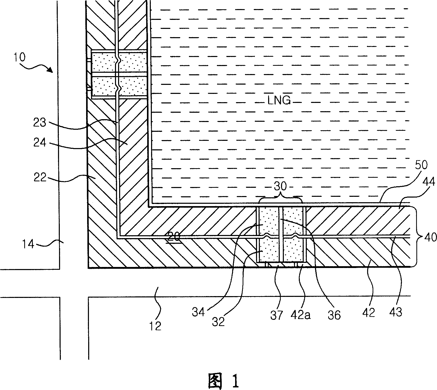
[0034] Hereinafter, the configuration of the present invention will be described in detail with reference to the accompanying drawings.

[0035] The present invention is directed to liquefied natural gas storage tanks in which liquefied natural gas (LNG) is stored at high pressure and extremely low temperature. For this reason, LNG storage tanks are constructed so that shock resistance and liquid-tight characteristics are firmly maintained.

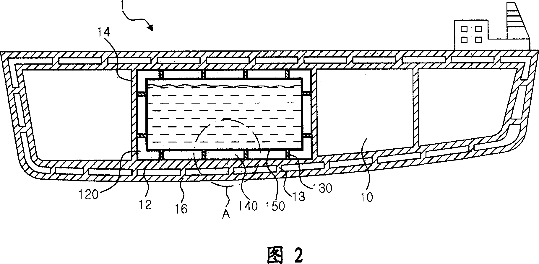
[0036]LNG storage tanks mounted to cars or ships, where the cargo is movable, differ from ground storage tanks with little movement, as suitable countermeasures should be prepared to resist the mechanical stress due to the movement of the cargo in the tank. However, LNG storage tanks installed to ships providing countermeasures against mechanical stress can also be applied to surface storage tanks. Accordingly, this document describes, by way of example, the configuration of an LNG storage tank installed to a vessel.

[0037] FIG. 2 is ...


PUM


Abstract

The invention relates to a liquefied natural gas storage tank with improved separation structure and a manufacture method thereof; furthermore, the liquefied natural gas storage tank is arranged in the structure such as a ship, a ground storage tank, a vehicle and similar objects. The invention aims at providing the liquefied natural gas storage tank with the improved separation structure and the manufacture method thereof; wherein, the sealing reliability can be increased by simplifying the structure of the separation body and a sealing wall and the assembly mechanism between the sealing walls and improving the assembly operation; furthermore, the time that is used for constructing the storage tank can be reduced by simplifying the manufacture structure and the process. In order to achieve the objects of the invention, the invention provides the liquefied natural gas storage tank with the improved separation structure. The invention comprises the separation wall which is arranged on the internal wall of the storage tank, the sealing wall which is arranged on the upper surface of the separation wall and is directly contacted with the liquefied natural gas, and a plurality of anchorage structures which are arranged on the internal wall of the storage tank so as to supporting the sealing wall by passing through the separation wall.

Description

technical field [0001] The present invention relates to a liquefied natural gas (LNG, liquefied natural gas) storage tank having an improved insulation structure and installed in structures such as ships, ground storage tanks, vehicles and the like, and a manufacturing method thereof. More specifically, the present invention relates to a liquefied natural gas storage tank having an improved insulation structure and a method of manufacturing the same, in which the manufacturing process can be shortened by simplifying the structure of the liquefied natural gas storage tank for storing cryogenic liquid, and can also be stably Maintain liquid-tight properties. Background technique [0002] Generally, liquefied natural gas (LNG) is obtained by liquefying natural gas, one of fossil fuels. The liquefied natural gas storage tanks are classified into: ground storage tanks, which are installed on the ground or buried in the ground according to installation locations; and mobile stora...

Claims


Application Information

Patent Timeline
Patent Type & Authority Applications(China)
IPC IPC(8): F17C1/02
CPCF17C2221/033Y10T29/49826F17C13/001F17C2270/0178F17C2203/0333F17C2260/033F17C2205/0119F17C2209/221F17C2209/228F17C2203/0631F17C2223/033F17C2223/0161F17C2270/0105F17C2203/012F17C2260/013F17C2203/0619F17C2201/0166F17C1/12
Inventor 梁永明尹仁铢杨泳哲金映均
Owner KC LNG TECH CO LTD ENTIRE RIGHT
Why Eureka
Try Eureka