Joint member

A joint groove and connector technology, applied in the field of joints, can solve problems such as construction trouble, joint design problem, peeling of sealing material 97, etc., and achieve the effects of high water cutoff, low manufacturing cost, and easy construction.

Inactive Publication Date: 2007-10-31
NICHIHA CORP
View PDF1 Cites 7 Cited by
  • Summary
  • Abstract
  • Description
  • Claims
  • Application Information

AI Technical Summary

Problems solved by technology

[0008] In the construction structure shown in FIG. 7 , the durability of the sealing material 97 is a problem, and the sealing material 97 may be peeled off due to the infiltration of rainwater.
In addition, since the sealing material 97 is filled between the upper and lower outer wall panels 30A and 30B, a joint groove having a certain depth cannot be formed, which causes a slight problem in the design of the joint portion.
[0009] In the construction structure shown in Figure 8a, it is necessary to adjust the distance between the ends of the upper and lower outer wall panels 30A, 30B, that is, it is necessary to adjust the positions of the outer wall panels 30A, 30B so that the joint width becomes a desired certain width, Therefore, the construction is very troublesome
In addition, the dripping portion 53 of the middle dripping groove 50 covers the front surface of the upper end portion of the lower outer wall panel 30B, and the joint groove cannot be in a straight line in the horizontal direction, but the surface patterns of the upper and lower outer wall panels 30A, 30B are restricted Appearance of the drip part 53 separated
[0010] In the construction structure shown in Fig. 8b, the shape of the middle drip groove 60 is complicated, and in order to support the weight of the upper outer wall panel 30A, the middle drip groove 60 must be made of an aluminum molded product, etc., resulting in an increase in cost

Method used


Image

  • Joint member
  • Joint member
  • Joint member

Examples


Embodiment Construction

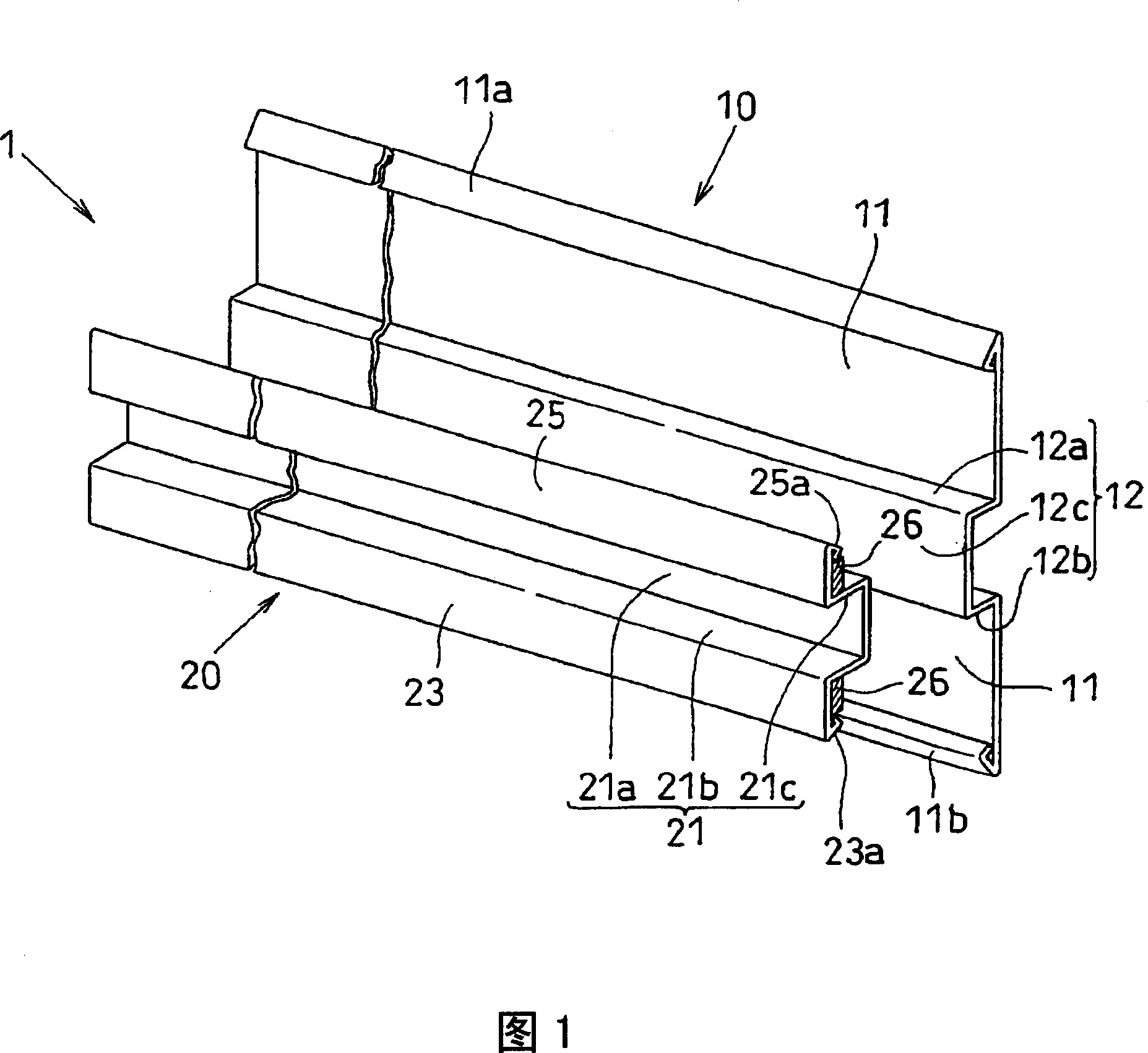
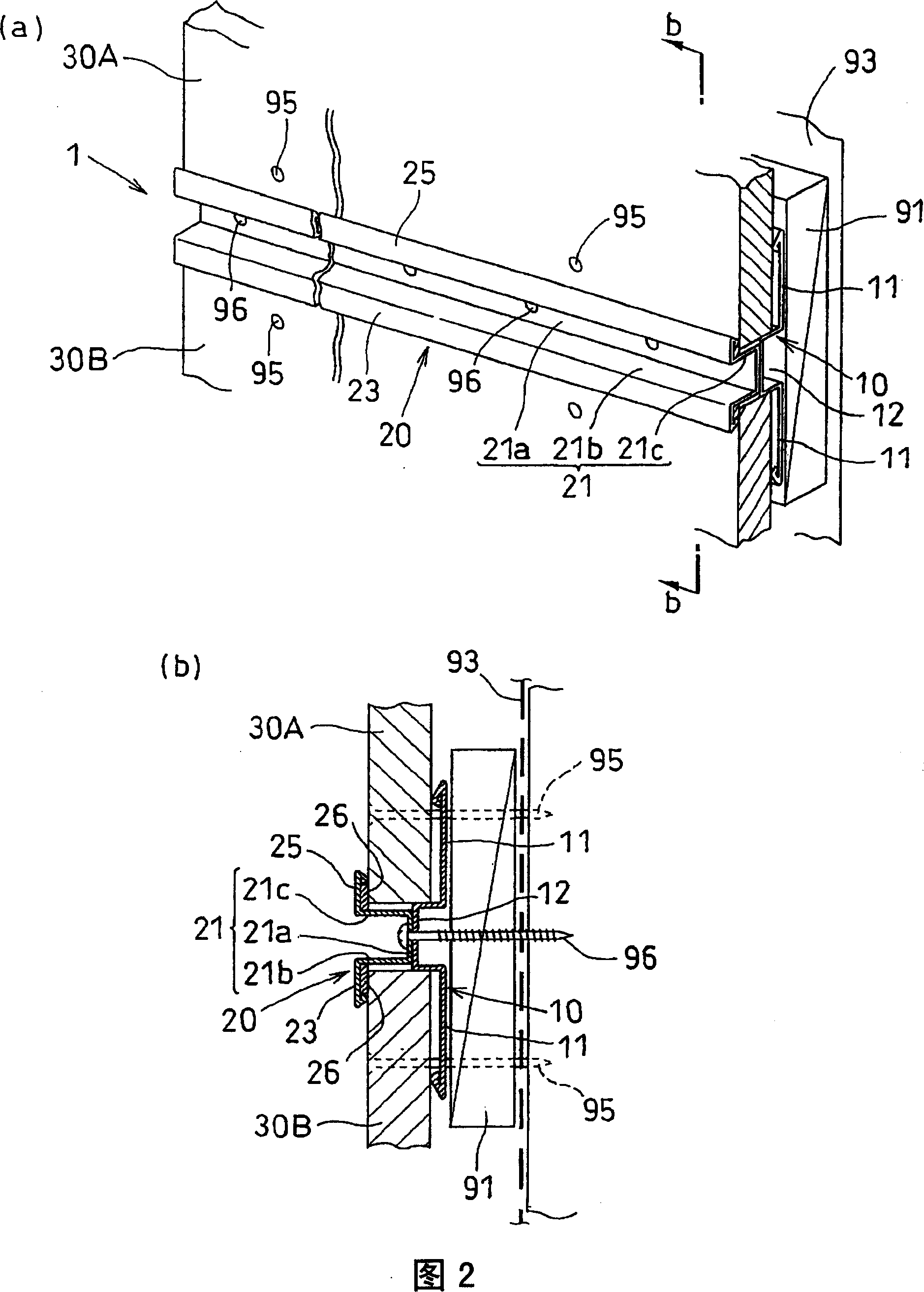
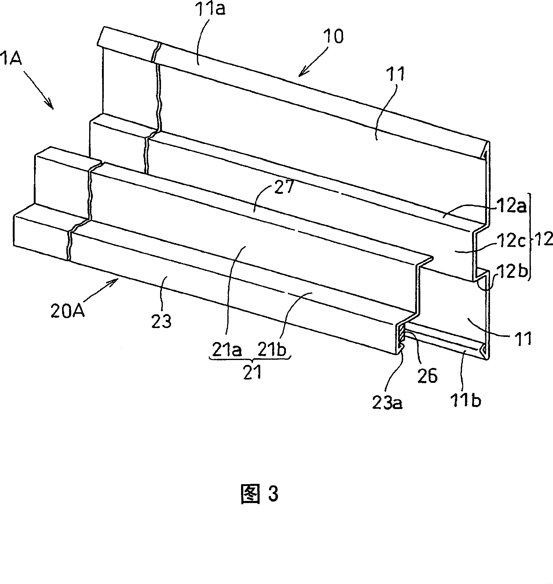
[0031]Hereinafter, preferred embodiments of the present invention will be described with reference to the drawings. 1 is a perspective view showing a joint material according to an embodiment of the present invention; FIG. 2a is a perspective view showing a construction structure using the joint material shown in FIG. 1;

[0032] In the construction structure of the outer wall shown in FIG. 2 , the outer wall panels 30A, 30B are attached to the horizontal bar 91 by driving nails 95 from the surface side, and the joint 1 is fixed between the upper and lower outer wall panels 30A, 30B. . The seam 1 is composed of two members shown in FIG. 1 , namely, a hat connector 10 and a seam cover 20 , and either of them is formed by performing sheet metal working on a sheet of steel plate.

[0033] First, the hat connector 10 is composed of a substrate 11 serving as a fixing surface fixed to the horizontal bar 91 , and a convex portion 12 formed by bending the vicinity of the center in th...


PUM


Abstract

A joint piece (1) comprises a hat-like connecting piece (10) and a joint covering piece (20), wherein the hat-like connecting piece (10) comprises a base plate (11) fixed on the side framework of an architecture and a boss (12) projecting from the base plate (11) to the side of the architecture surface, while the joint covering piece (20) comprises a joint groove piece (21) for covering a top side (12c) of the boss (12) in construction, a lower margin piece (23) which is extended upon from the lower end of the joint covering piece (20) thereby pressing and connecting an outer wall plate (30B) in construction, and an elastic water division piece (26) pasted on the back of the lower margin piece (23), therefore the joint piece can be provided with low cost and simple construction, and can have high design performance and high water division property.

Description

technical field [0001] The present invention relates to a joint that is fixed between upper and lower adjacent outer wall panels when the outer wall panels are installed on the outer wall of a building. Background technique [0002] In order to improve the design of the building's outer wall, external wall panels such as ceramics, which have been subjected to surface pattern treatment such as natural stone style / brick tile style, are often attached to the outer wall of the building. The installation method of the outer wall panel includes the horizontal installation method of attaching the longitudinal direction of the outer wall panel to the frame side as the horizontal direction (horizontal direction), and the vertical installation method of attaching the longitudinal direction of the outer wall panel to the frame side as the longitudinal direction (vertical direction) . Usually, the upper and lower end faces of the outer wall panels adopting the longitudinal installation...

Claims


Application Information

Patent Timeline
Patent Type & Authority Applications(China)
IPC IPC(8): E04F13/21E04F13/076
Inventor 伊藤博
Owner NICHIHA CORP
Why Eureka
Try Eureka