
Method of producing connecting rod with bearing, and connecting rod with bearing

A bearing pad and connecting rod technology, applied in the direction of manufacturing tools, bearings, connecting rods, etc., can solve the problems of peeling, the reduction of the connection strength of the metal layer of the bearing pad, and the reduction of the connection strength of the bearing pad and the connecting rod, so as to improve the output power, The effect of overall size and weight reduction, heat transfer and heat dissipation capability improvement

Inactive Publication Date: 2007-10-31
JAPAN SCI & TECH CORP +1
View PDF2 Cites 12 Cited by
  • Summary
  • Abstract
  • Description
  • Claims
  • Application Information

AI Technical Summary

Problems solved by technology

However, when using the spraying process, if the material of the connecting rod is unqualified, it will reduce the connection strength (bondingdegree) between the bearing pad and the connecting rod
In addition, because the metal layer of the bearing pad formed by spraying is not mixed with the material of the connecting rod, the peel strength of the metal layer is relatively low
[0008] In addition, when the metal layer of the bearing pad is formed by the spraying method, the spray gun cannot be inserted into the fitting hole (ie, the small end hole) of the small end portion of the connecting rod, so the bearing pad metal material has to be sprayed in an oblique direction, resulting in The connection strength of the metal layer of the bearing pad is reduced, even causing peeling or fracture

Method used


Image

  • Method of producing connecting rod with bearing, and connecting rod with bearing
  • Method of producing connecting rod with bearing, and connecting rod with bearing
  • Method of producing connecting rod with bearing, and connecting rod with bearing

Examples


Embodiment Construction

[0036] Hereinafter, embodiments of the present invention will be described in detail with reference to the accompanying drawings.

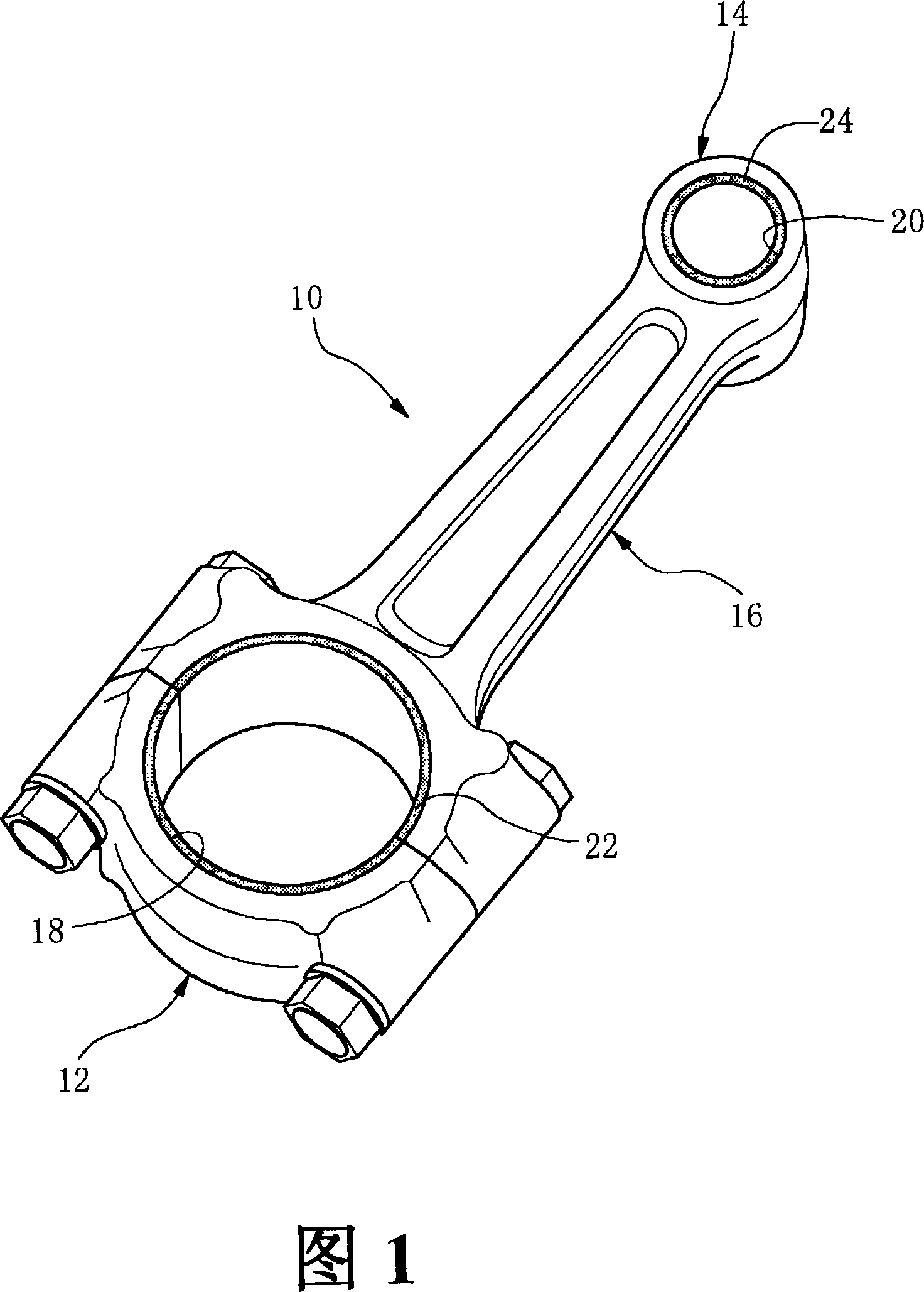
[0037] In FIG. 1 , reference numeral 10 denotes a connecting rod comprising a large end portion 12 , a small end portion 14 , and a rod portion 16 located between the two end portions 12 , 14 .

[0038] The large end portion 12 has a large end hole 18 (ie, fitting hole) in which a crank pin is installed, and the small end portion 14 has a small end hole 20 (ie, fitting hole) in which a piston pin is fitted. . Thus, the crankpin is connected to the large end portion 12 such that the crankpin is rotatably mounted in the large end bore 18 and the piston pin is connected to the small end portion 14 such that the piston pin is rotatably mounted in the small end bore 20 .

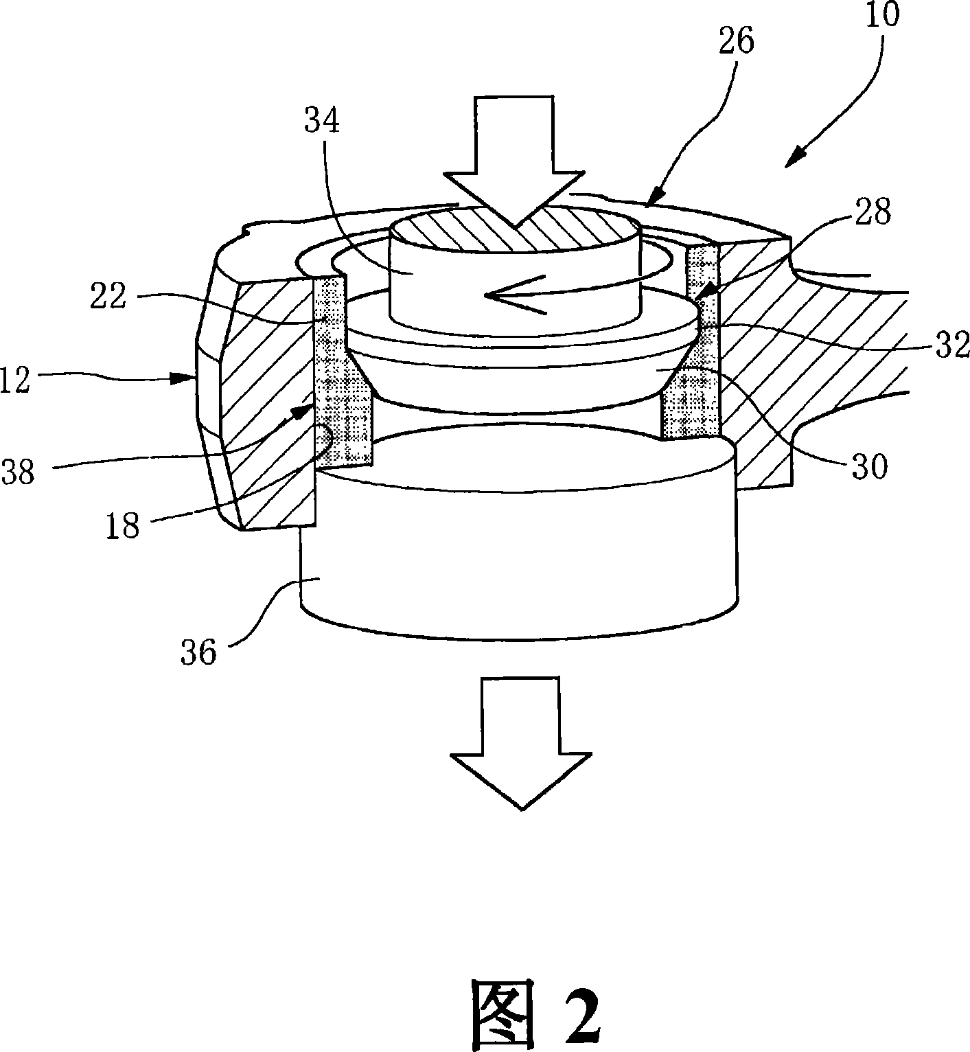
[0039] On the inner surface of the large end hole 18, a bearing pad metal layer 22 is directly connected and formed, which has a corresponding cross-sectional shape and is cylindric...


PUM


Abstract

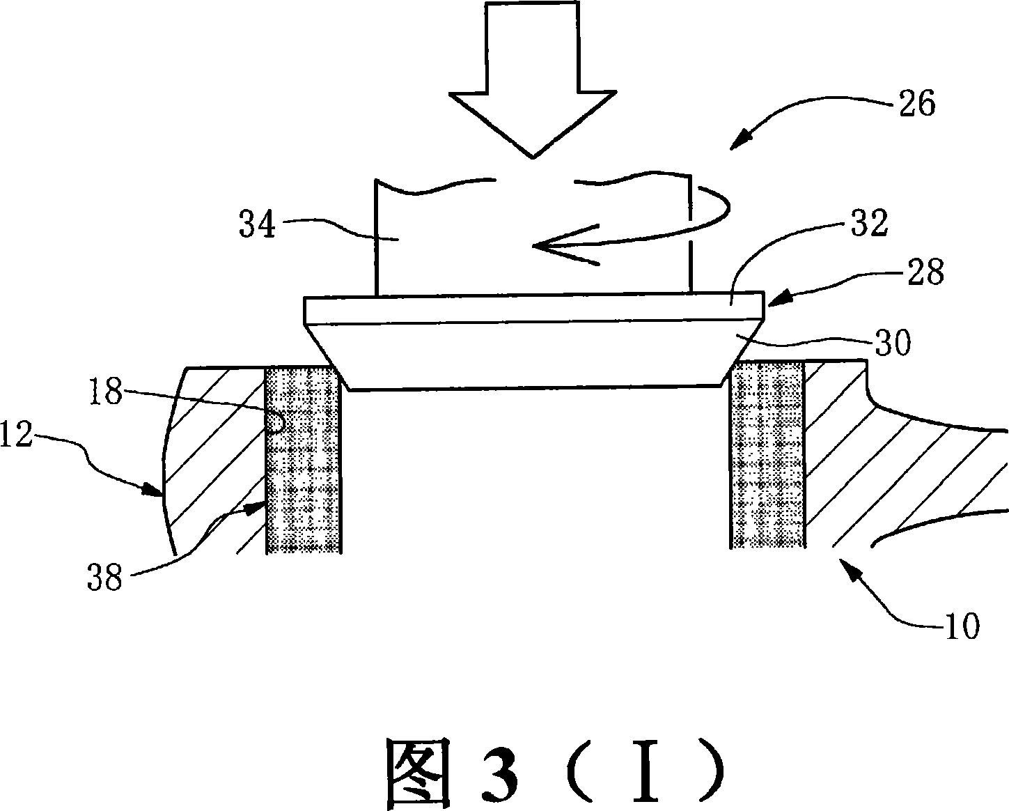
A method of producing a connecting rod with a bearing, in which both a process for producing a bearing separately from a connecting rod and a process for assembling the bearing to the connecting rod can be eliminated to reduce processes, labor, and costs to produce the connecting rod. A hollow cylindrical molding (38) of a bearing metal material is inserted and fitted, as an inner member, inside an inner surface of a circular large end hole (18) of a large end section (12) of a connecting rod (10). A tapered surface (30) of a rotary pressing tool (26) is pressed, while rotating, to the hollow cylindrical molding (38) to heat and soften the hollow cylindrical molding (38), causing the hollow cylindrical molding (38) of the bearing metal material to plastically flow axially and radially outward, whereby a bearing metal layer (22) is directly joined and formed on the inner surface of the large end hole (18).

Description

technical field [0001] The invention relates to a method of manufacturing a connecting rod with a bearing shell or bearing shells, and to a connecting rod with a bearing shell or multiple bearing shells. Background technique [0002] A connecting rod connecting a piston and a crankshaft of a vehicle engine includes a large end portion on the crankshaft side, a small end portion on the piston side, and a rod portion between the two ends. The small end part has a circular fitting hole (that is, a small end hole) in which a piston pin (a pisoton pin) for connection is rotatably installed; the big end part has a fitting hole (that is, a big end hole) in which a crank pin (a crankpin) for connection is rotatably mounted. [0003] A con rod bearing is fitted with the inner surfaces of the opposite connecting rod fitting holes of the large end portion and the small end portion of the connecting rod, the bearing bearing is cylindrical as a whole, and the crank pin and the piston pi...

Claims


Application Information

Patent Timeline
Patent Type & Authority Applications(China)
IPC IPC(8): F16C7/02B23K20/12F16C9/04F16C17/02F16C33/14
CPCF16C33/08B23K20/1295B23K20/129B21J5/063B23K2201/006B23K20/1225F16J7/00F16C9/04F16C33/14B23K2203/16B23P15/00B23P2700/04F16C2360/22F16C2226/12F16C2226/60B23K2101/006B23K2103/16Y10T74/2142Y10T74/216Y10T29/4929Y10T29/49288Y10T29/49291F16C17/022
Inventor 村上秀树篠田刚南部圭司
Owner JAPAN SCI & TECH CORP
Learn More