
Telescope and pan-focal telescope comprising plan convex or plan concave lenses and deflecting means connected thereto

A telescope and lens technology, applied in the field of pan-focus telescopes, can solve the problems of increased reflection loss, inaccuracy, beam instability, etc.

Active Publication Date: 2007-10-31
LEICA GEOSYSTEMS AG
View PDF4 Cites 2 Cited by
  • Summary
  • Abstract
  • Description
  • Claims
  • Application Information

AI Technical Summary

Problems solved by technology

In addition to this beamsplitter, the coupling-in mirror for coupling in the measuring beam in the tachymeter telescope has to be fixed by means of a bracket, with the result that the already mentioned inaccuracies such as beam instability etc. again occur
With each additional element, there is an increased risk of disturbing environmental effects, but also the disadvantage of loss of reflection
A substantial disadvantage is the space required for each individual component and the resulting greater construction length of the optics

Method used


Image

  • Telescope and pan-focal telescope comprising plan convex or plan concave lenses and deflecting means connected thereto
  • Telescope and pan-focal telescope comprising plan convex or plan concave lenses and deflecting means connected thereto
  • Telescope and pan-focal telescope comprising plan convex or plan concave lenses and deflecting means connected thereto

Examples


Embodiment Construction

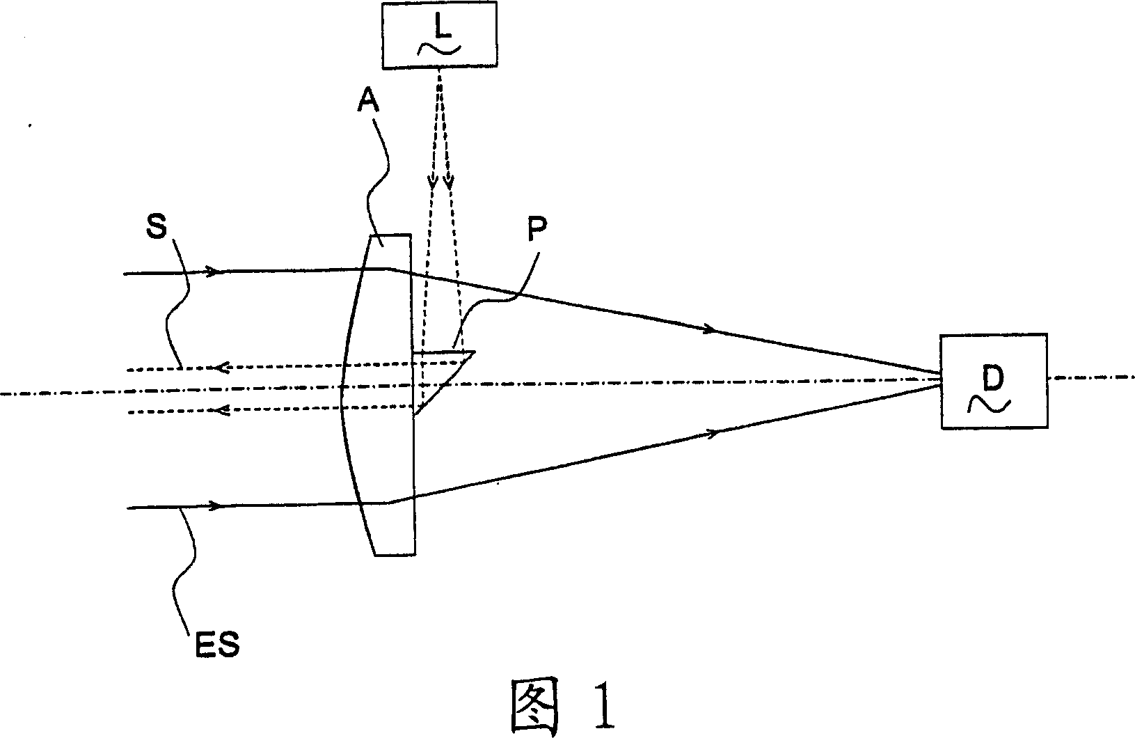
[0036] FIG. 1 shows a laser range finder known from the prior art described above.

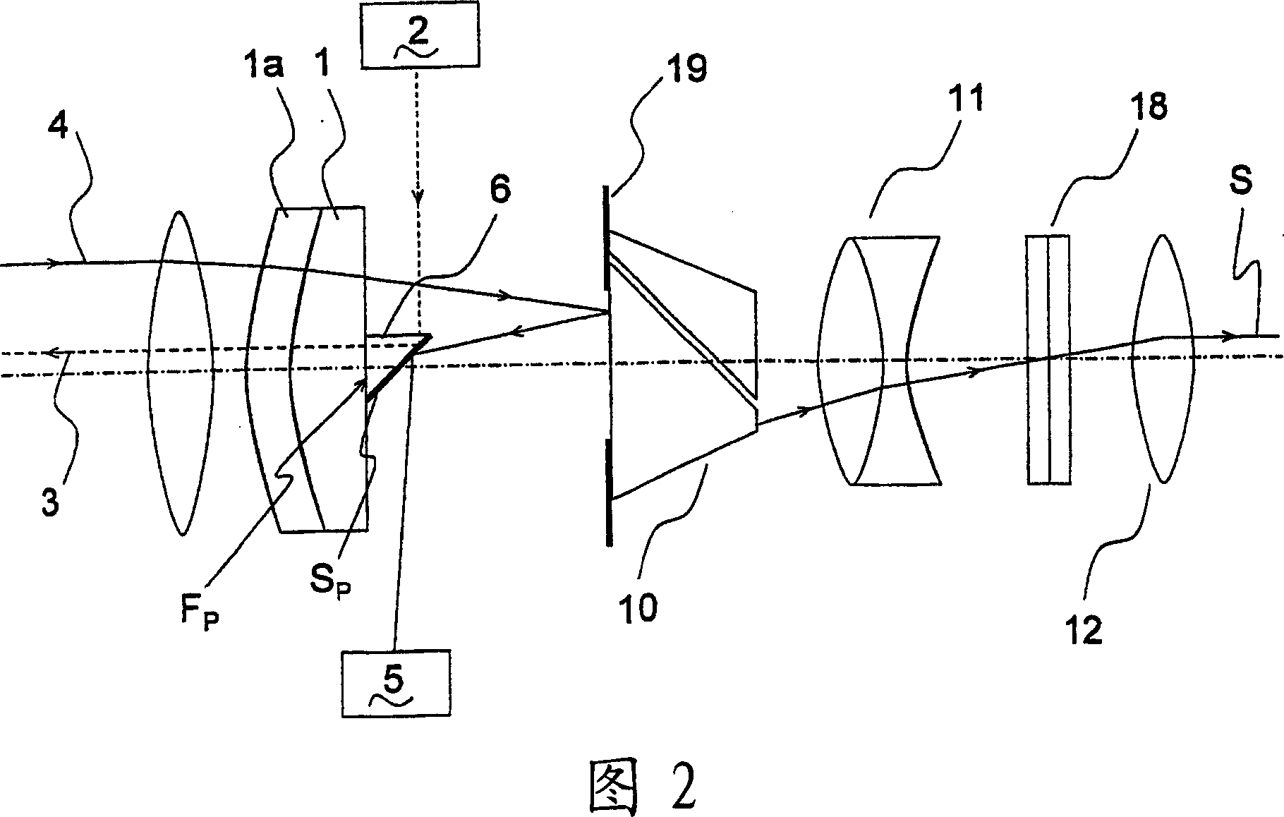
[0037] Fig. 2 shows a telescope according to the present invention, the lens 1 of the objective lens unit of the telescope is a plano-convex lens. A planar optical deflecting member, shown as a prism 6, is mounted on the planar surface of the lens 1 and serves to reflect a measuring beam, for example for a distance meter, into and in a compact, coaxial and stable manner. Reflects off the optical axis of the telescope. Prism 6 has a mirror surface S p , which can be reflected relative to the wavelength of the measurement beam. To be installed or connected: the connection part, the lens 1 and the prism 6 form a substantially integrated part. The connection of the prism 6 to the lens 1 is realized by cement connection, that is, the light-transmitting cement connects the plane surface F of the prism 6 pAttached to the flat surface of lens 1. The emission beam 3 emitted by the emission unit 2 ...


PUM


Abstract

The present invention relates to a telescope and pan-focal telescope comprising plan convex or plan concave lenses and deflecting means connected thereto, the telescope is used to inject and / or to extract, by reflection, emitting and / or capturing bundles of beams (3,4). According to the invention, at least one deflecting means (6) is joined to the planar surface by means of at least one lens (1) of the telescope objective unit, which is embodied as a plan convex or plan concave lens. The lens (1) is used as a lens (1) of the objective unit and as a holder for the deflection means (6). The number of optical components in the telescope about one of the holders is reduced due to the dual function thereof.

Description

technical field [0001] The invention relates to a telescope according to the preamble of claim 1 and a pan-focus telescope according to the preamble of claim 2 . Background technique [0002] The optical structure of a telescope is determined in particular by the function of the telescope, eg in relation to light intensity, image quality and focusing and magnification mechanisms. In contrast to optical measuring devices, e.g. optoelectronic rangefinders, which include light receivers for receiving light beams in telescopes that are received by the human eye, correspondingly very high-quality images are required for this purpose. The challenge posed to optical engineers is to produce a telescope with a short length but generally high image quality. To achieve this imaging quality, imaging errors such as spherical aberration, coma, distortion, and chromatic aberration need to be corrected. These corrections are achieved by the optical components, parameters such as lens curv...

Claims


Application Information

Patent Timeline
IPC IPC(8): G02B5/04G02B5/08G02B3/00G02B23/04G01B11/14G01C1/02
CPCG01C3/08
Inventor 安德烈亚斯·弗鲁曼托马斯·波日维尔于尔格·欣德林格
Owner LEICA GEOSYSTEMS AG
Features
  • Generate Ideas
  • Intellectual Property
  • Life Sciences
  • Materials
  • Tech Scout
  • Unparalleled Data Quality
  • Higher Quality Content
  • 60% Fewer Hallucinations
Learn More