
Magnetic sensor for input devices

A magnetic sensor and sensor technology, applied in the field of magnetic sensors, can solve problems such as changes, bridge imbalance, etc., and achieve the effect of simple materials and low cost

Active Publication Date: 2007-10-31
NXP BV
View PDF2 Cites 35 Cited by
  • Summary
  • Abstract
  • Description
  • Claims
  • Application Information

AI Technical Summary

Problems solved by technology

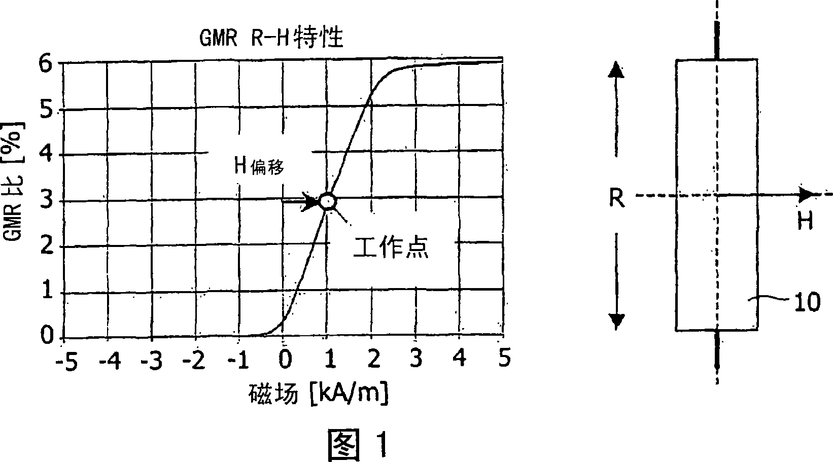
The bridge is unbalanced due to a change in the resistance of the sensor due to a change in the direction of the initially vertical magnetic field due to lateral movement of the joystick

Method used


Image

  • Magnetic sensor for input devices
  • Magnetic sensor for input devices
  • Magnetic sensor for input devices

Examples


Embodiment Construction

[0037] The present invention is described in detail by specific embodiments and with reference to the accompanying drawings, but the present invention is not limited by these embodiments and drawings except as limited by the claims. The drawings described are only schematic and not limiting. In the drawings, the size of some of the elements is exaggerated and not drawn on scale for illustrative purposes. Unless expressly stated otherwise, where an indefinite or definite article is used in reference to a singular noun, the plural of that noun is also included.

[0038] Furthermore, the terms first, second, third, etc. in the description and claims are used to distinguish similar elements, not to describe sequence or chronological order. It is to be understood that the terms so used are interchangeable under appropriate circumstances and that the embodiments of the invention described herein are capable of operation in sequences other than as described or illustrated.

[0039] B...


PUM


Abstract

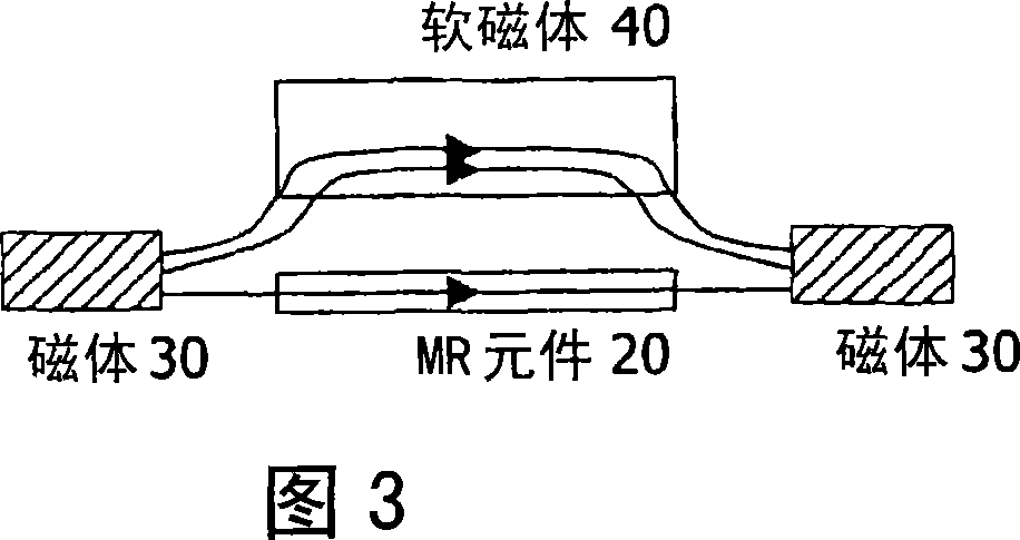
A magnetic sensor has a magnet (30) and a magneto-resistive element (20), arranged on a substrate such that magnetic field lines through the magneto-resistive element are substantially parallel to a plane of the substrate. Movement of a movable magnetically permeable element (40) near the substrate is detected as it alters the number of field lines through the element. The sensor can be more sensitive than devices arranged with perpendicular field lines, and can be easier to manufacture and integrate. Applications include analog pointers, pressure sensors and microphones. The sensor can use magnets placed either side of the element to detect changes in size of a gap above the element. As the gap closes, less of the parallel oriented field passes through the magneto resistive element.

Description

technical field [0001] The present invention relates to magnetic sensors for sensing motion and / or position, to modules including such sensors, to pressure sensors, to microphones, to accelerometers and to computer input devices incorporating such magnetic sensors, and to the manufacture of such sensors or method of the module. Background technique [0002] Especially in portable PCs and small handheld devices like mobile phones, PDAs, digital cameras or GPS devices, devices that simulate pointing functions (joysticks) are required. Such a device is more complex than a discrete pointing device, which simply acts as a switch in two main directions (X and Y). Various known such devices are eg piezoelectric devices, optical pointing devices or devices based on strain measurement. Piezoelectric and strain measurement indicating devices require complex microcontrollers to compensate for sensor drift. Optical pointing devices such as the Philips Laser Beetle are feasible, but c...

Claims


Application Information

Patent Timeline
Patent Type & Authority Applications(China)
IPC IPC(8): G06F3/033G01R33/09G06K11/00G05G9/047H01L43/08H01F10/32G01B7/00G01L9/00G11B9/00G11B5/39G01D5/12G06F3/0338H10N50/10
CPCG01R33/096B82Y25/00G01D5/147G01L1/14G01L5/223G01R33/093G05G2009/04755G11B5/39H01F10/324H03K2217/96011H01L2224/48091H01L2224/48247H01L2924/181H01L2924/1815H01L2924/00014H01L2924/00012G01R33/09
Inventor 汉斯·范索恩亚普·鲁伊格罗克让·C·范德霍芬
Owner NXP BV
Learn More