
Optical identification element and display device containing the same element

An optical and component technology, applied in the field of optical recognition components and displays including the components, can solve problems such as the decline of optical recognition rate

Active Publication Date: 2007-11-07
AU OPTRONICS CORP
View PDF0 Cites 3 Cited by
  • Summary
  • Abstract
  • Description
  • Claims
  • Application Information

AI Technical Summary

Problems solved by technology

However, there will be stray light reflected by the glass mirror in the gap between the multilayer films, resulting in a decrease in optical recognition

Method used


Image

  • Optical identification element and display device containing the same element
  • Optical identification element and display device containing the same element
  • Optical identification element and display device containing the same element

Examples


Embodiment Construction

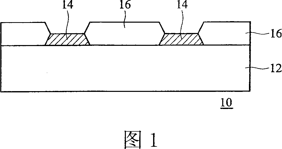
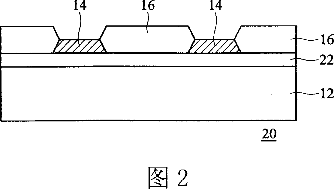
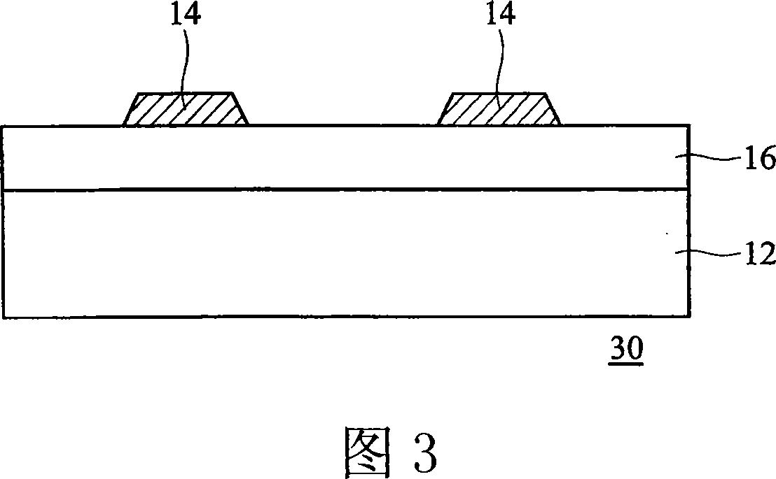
[0039] The invention provides an optical identification element, comprising: a transparent substrate; a patterned multilayer film formed on the transparent substrate; and an anti-reflection optical film formed in the gap of the patterned multilayer film.

[0040] FIG. 1 is a schematic cross-sectional view of the optical identification element of the present invention. Please refer to FIG. 1 , the optical identification element 10 includes a transparent substrate 12 , a patterned multilayer film 14 and an anti-reflection optical film 16 . The patterned multilayer film 14 is formed on the transparent substrate 12 for reflecting an infrared light and penetrating a visible light for reflecting a recognition pattern, and the anti-reflection optical film 16 is formed in the gap 18 of the patterned multilayer film 14 .

[0041] The above-mentioned transparent substrate 12 can be a glass substrate. The patterned multilayer film 14 is an infrared reflective film, which can be made of...


PUM


Abstract

The invention discloses an optical recognition component, comprising: a transparent substrate; a patternized multi-layer film formed on the transparent substrate; and an antireflecting optical film formed in the gaps of the patternized multi-layer film. And the invention also provides a display unit comprising the optical recognition component, comprising: a display panel having a transparent substrate; a patternized multilayer film formed on the transparent substrate and an antireflecting optical film covering the gaps of the patternized multilayer film. And the invention advances a handwriting input device suitable for various flat panel displays, on the condition of not influencing the output pictures of the original displays, able to be used for the optical recognition device to clearly locate the relative position and able to improve optical recognition ratio.

Description

technical field [0001] The invention relates to an optical element, in particular to an optical identification element and a display comprising the element. Background technique [0002] Traditional handwriting input man-machine interfaces or display panels can be classified into resistive, capacitive, inductive, or optical types. These handwriting devices provide no keyboard or other bulky input devices. [0003] However, these technologies are not ideal in terms of resolution and response time, making it impossible to perform precise positioning on the man-machine display interface or achieve fast handwriting input. In order to overcome the above shortcomings, many companies have continued to develop related technologies in recent years. For example, the electromagnetic induction handwriting input panel developed by Wacom can almost achieve the effect of handwriting input, but it is not popular because of its high price. The existing optical identification method is to us...

Claims


Application Information

Patent Timeline
Patent Type & Authority Applications(China)
IPC IPC(8): G02B1/11G02B1/00G09F9/00
Inventor 陈佩瑜郑胜文廖烝贤
Owner AU OPTRONICS CORP
Learn More