Computer electric source

A technology of computer power supply and power supply circuit, applied in the field of power supply, can solve the problems of low heat dissipation efficiency of computer power supply, inability to get rid of traditional methods, low heat transfer efficiency, etc., and achieve the effect of favorable heat dissipation, cost reduction and high power

Inactive Publication Date: 2007-11-07
张文
View PDF0 Cites 6 Cited by
  • Summary
  • Abstract
  • Description
  • Claims
  • Application Information

AI Technical Summary

Problems solved by technology

In the existing solutions, some use heat pipes to guide the heat from the internal radiator to the finned shell, and some add silicone gaskets between the internal radiator and the finned shell to transfer heat. But still can't get rid of the traditional way of adapting the heat sink to the circuit board. The huge shell is only used as the finned part of the "T" shape heat sink
The low efficiency of heat transfer from power electronic components to the finned case is a bottleneck that is difficult to break through in the current method of fanless computer power supplies that use the case to dissipate heat.
Therefore, under the same external dimensions, the power of the existing fanless computer power supply is difficult to be as large as that of the fan computer power supply.
[0008] It can be seen that in the prior art, a more complex structure must be adopted to guide the heat of the power electronic components of the circuit board to the finned housing. The excessively long conduction path leads to low heat transfer efficiency, so the heat dissipation of the computer power supply The efficiency is low, and the advantage of using the heat dissipation of the shell cannot be fully utilized

Method used


Image

  • Computer electric source
  • Computer electric source
  • Computer electric source

Examples


no. 1 example

[0041] Fig. 4 and Fig. 6 are three-dimensional exploded view and combined schematic diagram respectively of this embodiment, mainly include parts such as sub-circuit board 10, main circuit board 20, upper case 30 and lower case 40, and upper case 30 and lower case The casing 40 constitutes an example of a power supply casing in the embodiment of the present invention, and the outer wall of the upper casing 30 includes cooling fins. in:

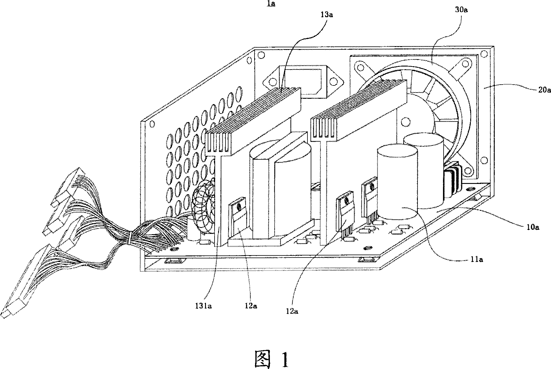
[0042] The electrical connector connecting the sub-circuit board 10 and the main circuit board 20 is made of a plug and a socket with flexible wire bundles, including at least two electrical connectors, one (plug 14, socket 22) is connected with the switching element 11 and the switching transformer 13 primary relevant circuits, one (plug 15, socket 23) is connected with rectifying element 12 and the secondary relevant circuit of switching transformer 13. The specification of the electrical connector depends on the power of the power supply. ...

no. 2 example

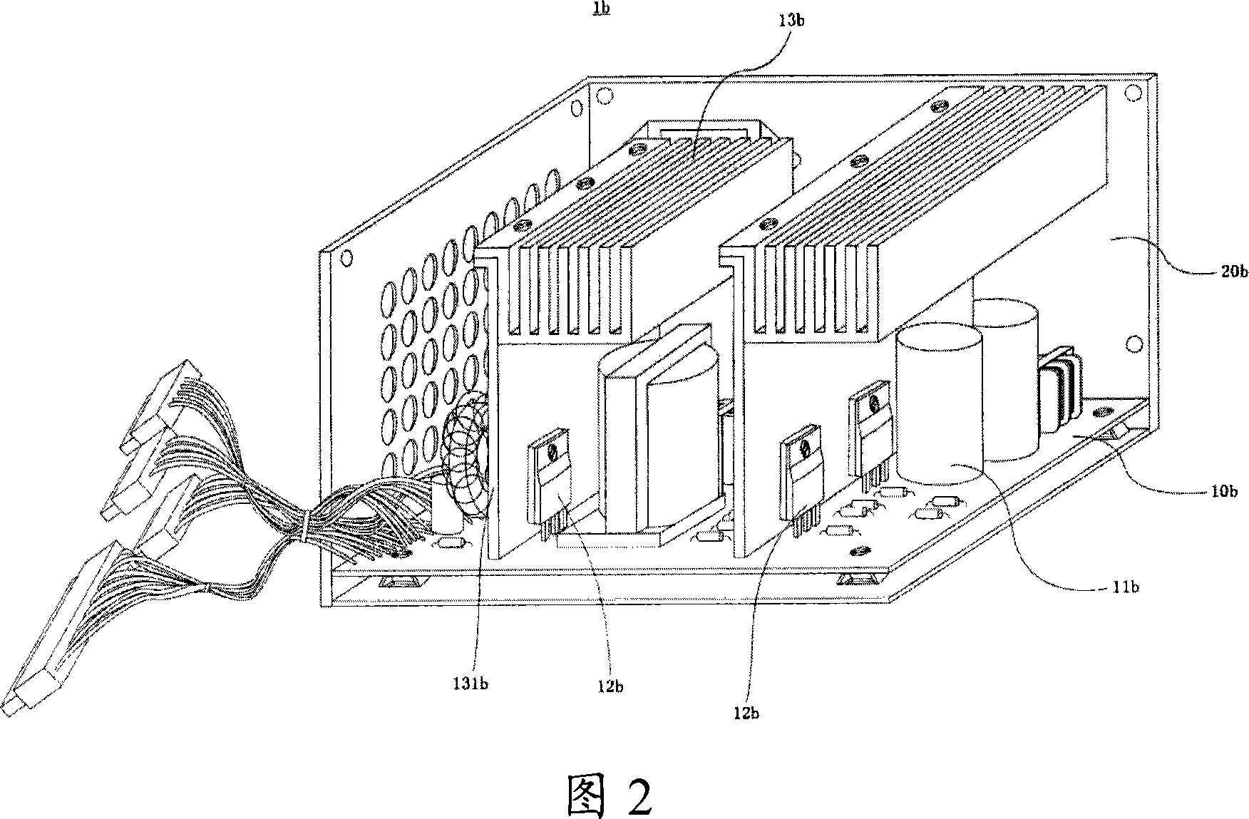
[0052] This embodiment is an embodiment of the computer power supply under the general power demand. In this case, the heat dissipated by the inner wall of the upper casing is relatively small, so even if a sub-circuit board with a relatively small size is used, it is the embodiment of this embodiment. In the sub-circuit board 50, the internal temperature of the power supply can also be maintained at a normal level.

[0053] Because the difference between the second embodiment and the first embodiment only lies in: the shape and size of the sub-circuit board are different; The installation location is different. Therefore, only the differences from the first embodiment will be introduced below, and the rest can refer to the relevant content in the first embodiment.

[0054] Fig. 5 and Fig. 6 are three-dimensional exploded view and combined schematic diagram respectively of this embodiment, mainly include components such as sub-circuit board 50, main circuit board 20, upper ca...


PUM


Abstract

The invention discloses a computer power supply, comprising: a case whose outer wall is equipped with heat radiating fins; sub circuit board equipped with power electronic components and related electronic components of power supply circuit and arranged on the top inner wall of the case and the bodies of the power electronic components are fixed on the top inner wall of the case; a main circuit board, equipped with the other electronic components and arranged inside the case and connected with the sub circuit board. And the advantages of the invention: no fan noises, good heat radiating performance and high power, lower internal temperature and not high cost.

Description

technical field [0001] The invention relates to a power supply, in particular to a power supply for a computer. Background technique [0002] The circuit of the computer power supply contains various electronic components, among which the switching element, the rectifying element, etc. are high-heating power electronic components, and the component body is fixed on the radiator, and is installed on the circuit board through the pins on the component body. Since the computer power supply has a standard external dimension (140mm×150mm×86mm), after the circuit board full of electronic components is installed in the housing, there are various shortcomings and disadvantages in the remaining space with the general heat dissipation scheme. [0003] Existing computer power supplies usually use "T" or inverted "L" heat sinks, which have an upright part without fins, which can be installed upright on the circuit board like ordinary electronic components without occupying too much spac...

Claims


Application Information

Patent Timeline
Patent Type & Authority Applications(China)
IPC IPC(8): G06F1/18G06F1/26
Inventor 张文
Owner 张文
Why Eureka
Try Eureka